Improving the process of repair of the aircraft panels made of composite materials
Introduction
Uzbekistan is a country with the
aviation world renownbeginning of our aviation became from 90th
years.28, 1992 was established by the Decree of the President Islam Karimov
Airline as governmental body for civil aviation ensure the development,
coordination and implementation of policy in the field of air transport on the
territory of the Republic of Uzbekistan.airline "Uzbekiston
havoyullari" - the state airline of Uzbekistan, providing the needs of the
economy and the population in the aviation services (freight, passenger,
special aerial work).main functions of the airline are to provide quality
services to local and international airlines, the research and implementation
of new technologies and scientific developments in the field of air
transport.has the status of association, consisting of structural units having
the rights of legal persons, and operates on the principles of cost accounting,
self-financing and self-sufficiency. NAC «Uzbekiston havoyullari» is fixed and
current assets, independent and consolidated balance sheet, and other accounts
in banking institutions in Uzbekistan and abroad., on the air line out West
European Airbus A-310 -300, Boeing - 757 and 767.14 international routes. Given
the charter flights, experts Metropolitan Airport service aircraft with flights
to almost all Asian and European countries.in world practice was performed trouble-free
operation and maintenance of aircraft outside the Republic.experience has
allowed to start as soon as possible on ships flying the A- 310 - 757 and
Boeing 767. So, the airport "Tashkent" got great potential in the
international market of aviation services.the mid-90s, with the support of
companies "Strabag", "Fox" and the airport Frankfurt -
Main, began work on the reconstruction of the global "northern" and
"southern" runways, installed the latest lighting system of
production "Siemens", thanks what airport was the second category of
ICAO.2001 Tashkent airport complex has been completely renovated, which allowed
him to become one of the largest and most comfortable, it is equipped with the
latest technology and is capable of high-quality service and passengers,
almost, all types of aircraft operating in the world.«Uzbekiston havoyullari»
flies on a regular basis in more than 40 cities in the world - in Europe and
Asia, America and Japan. Representation of airlines operating in 25
countries.NAC fleet consists of western aircraft Boing-757/767, A320, modern
liners domestic production of IL-114 -100, as well as cargo aircraft A300-600.
For airworthiness and provide the necessary qualifications aircrew airline has
its own training complex, in which modern procedural simulators aircraft
Boeing-757/767, A320 and unikalny full - light - simulator IL-114-100. In 2016,
planned to receive new-generation aircraft Boeing- 787 -8 Dreamliner, in
connection with what is being created on the basis of aircraft repair NAC
«Uzbekistan airways technics» first in Central Asia regional workshop of the
major elements of aircraft structures made of composite materials. The
composite material (composite) - structural (metallic or non-metallic)
material, in which there are reinforcing elements in the form of its yarns,
fibers or flakes more durable material. Examples of composite materials
reinforced plastic Born, carbon, glass fiber bundles or tissues based on them;
aluminum reinforced with steel strings, and beryllium. Combining the volume
content of components can receive composite materials with the required
strength, heat resistance, modulus of elasticity, abrasion resistance, and
create a composition with the necessary magnetic, dielectric, radio absorbing
and other special properties.11 airports included in the airlines today have
international status. In NAC «Uzbekiston havoyullari» employs more than 14
thousand employees.'s business strategy is to implement a program of civil
aviation development, providing for the modernization and unification
samoleto-motornogo park, construction of new airport complex reconstruction of
air traffic control systems, re airfields modern ground equipment, capacity
expansion own repair and technical base and the creation of its base training
of highly qualified personnel.the airline plans - start international airline
alliance SkyTeam.present, the services of the international airport
"Tashkent" resort recognized airlines such as:
• A/K "Lufthansa"
• A/K "Turk Hava Yullari"
• A/c "British Mediterrenien
Eyrueys"
• A/K «Aziana Eyrlaynz, INC"
• A/K "Korean Air"company
«P.T. GARUDA INDONESIA»
• A/c "Iran Air"
• of A/K «Transaero»«Aeroflot -
Russian Airlines»
• of A/K «Domodedovo Airlines»
• A/ B to "Siberia"
• GAOZT "Armenian
Airlines"
• A/K "AIR- XENA"
• A/ K "IMEYR"
• FSUE «Perm Airlines"
• CON RUE «Belavia"
• A / K "Altyn Air"
• SJC "Airlines of
Ukraine"
• NU "Turkmen"
• SAC "KAVMINVODYAVIA"
• JSC "Ural Airlines"
• SAC "Pulkovo"
• JSC «AIR KAZAKHSTAN»
• JSC "Aeroflot-Don"
• SUE A/K "Tatarstan"
• of A/K «Krasnoyarsk Airlines»
• of Zug "RusAero"
• JSC «Streamline OPS»A/K «East
Line» and othersengineering is based on the latest scientific and technical
achievements in all areas of modern knowledge, being essentially a catalyst for
scientific and technological progress in the field of basic sciences
(aerodynamics and gas dynamics, mechanics, solid state physics, etc.) and
applied research (materials science, instrumentation, electronics, avionics,
etc.) Modern aircraft and helicopters are designed and manufactured in
accordance with the special requirements safety and extremely harsh
environments: multiple repeatable peak loads, forced flight regimes in
all-weather and all-climate conditions, extreme temperatures, aerodynamic
nature of the external force. For modern civil aviation (main civil and
transport planes, planes for local airlines, multi-mission helicopters, etc.)
are essential to increase their resource, reducing the impact of aviation on
the environment, comfort, and to minimize the size of the aggregates. Solving
these problems is possible thanks to a new approach to the choice of structural
and functional materials based on the concept of integrated quality aircraft
materials. Integrated quality aircraft materials is determined by parameters
that are combined into several groups. Among them the most important are: the
weight efficiency, manufacturability (including operational), efficiency,
maintainability and testability, as well as several others. Weight efficiency
is mainly determined by the characteristics of strength, specific strength.the
lifetime and durability of aircraft allow the reliability characteristics of
the material, such as endurance and resistance to low-cycle fatigue, fatigue
crack growth rate, static and cyclic fracture toughness, resistance to stress
corrosion cracking, corrosion by stress, exfoliation corrosion and other forms
of corrosion, compatibility with other materials, opposition «effect Rebinder»
(adsorption decrease in strength, changes in the mechanical properties of
solids due to physico-chemical processes, causing a reduction in the surface,
the interfacial energy of the body, manifested in the reduction of strength and
fragility occurs, reducing durability; effect PA Rebinder opened in 1928).
Reliability of structures is largely determined by the resistance of the metal
spread existing fracture (fracture toughness), and not only its emergence.
1.
Constructive Part
- aerodyne with aerodynamic
principles of flight. Despite the variety of types, all aircraft have the same
basic units performing similar functions. Such units include wing, fuselage,
horizontal and vertical stabilizers, chassis and power plant.- the bearing
surface of the aircraft, designed to create aerodynamic lift, necessary to
ensure the flight and maneuver of aircraft in all modes. The wing is a
thin-walled shell backed and consists of a frame and cladding; frame - of
spars, stringers and walls and ribs. Located on the wing mechanization - slats,
flaps, ailerons, spoilers and pylons.- is bearing surfaces, which are bodies of
stability and controllability of the aircraft. It consists of horizontal and
vertical tail.construction being the basis of the aircraft structure combines
force with respect to a single entity all its parts.facilitate the work on the
production and operation of aircraft to devise a system partition on aircraft
parts - panel.the panel understood part of the outer surface of the unit or
section.forms the outer surface of the wing. From the quality of the wing
surface to a certain extent dependent on its aerodynamic characteristics. In
modern aircraft primary distribution received tough metal skin, as most fully
meets the requirements of aerodynamics, strength, stiffness, mass m. Metal
siding often made of sheets. Its thickness varies from 0.5 mm to very few
places have loaded the wing tip to 4...6 mm, and even more in highly stressed
areas in the root sections.most widespread modern airplanes received trim
high-strength aluminum alloys. On aircraft flying at high supersonic speeds (M
> 2), applies paneling resistant steels and titanium alloys, does not lose
its mechanical properties at elevated temperatures under aerodynamic heating
design.the shell plates to each other can be made lap with beveled edge, lap
and butt with crossovers. The simplest is the lap joint, but it causes the most
drag. Used to reduce the resistance lap joint with beveled edge and lap-joint
strike.joint may be made only to thin sheets of a thickness of 0.5... 1 mm.
Best aerodynamic relationship and get on the most widely used on modern
aircraft is the butt, although here and have to put at least two row riveted
joint, whereas in other schemes, you can do single-row suture stitch Rows
determined by the current load.joints are carried out by elements of the
framework: spars, stringers and ribs. Currently used for fastening cladding
countersunk riveting. Holes on the outer surface of the spleen on mortgage
countersunk head rivets. When riveting very thin sheets of thickness of 0.5...
0.6 mm holes for mortgage rivet head can be punch. In this case holes are punch
or spleen cells and those parts, which is a riveting trim.airplanes widely used
laminated paneling, consisting of two carrier layers interconnected lightweight
aggregate. Carriers cladding layers are made mostly of aluminum sheets. The
padding may be a cellular, or be constructed of porous corrugated sheet.
Honeycomb made from metal foil having a thickness of 0.03... 0.02 mm. Foils are
corrugated and are interconnected by gluing, soldering or spot welding.depends
on the shape of the comb corrugation. Honeycomb can be made of corrugated and
plastic tapes, glued between, a. Porous filler is made of porous plastic
materials having a low density. Sheathing with filer corrugated sheet are
receptive load whose direction coincides with the direction of the
corrugation.bearing sheets glued to a placeholder, and metal sheets and can be
soldered to a metal filler. In supersonic aircraft wings exposed to the aerodynamic
heating of large bearing cladding layers may be fabricated from titanium sheet
or sheets of heat-resistant steel, and the honeycomb core - of the same foil
material.paneling has a number of advantages compared with single-layered. A
laminated trim has larger lateral stiffness and consequently, high critical
strain. Thus, when the thickness of the carrier layer 5/2 = 1 mm and h = 10 mm,
the ratio is 75, and when h = 20 mm - 300. Approximately at the same ratio and
the transverse rigidity is increased. For this reason, laminated paneling not
need frequent stringer set, can significantly reduce the number of ribs.with
layered plating may be easier with a single-layer lining the wing, supported by
stringers. The surface quality of the laminated roof sheathing due to the lack
of riveted joints get higher. Laminated paneling has good insulating properties
that makes it profitable for its application subject to large aerodynamic
heating wings of supersonic aircraft, interior volumes are busy fuel.laminated paneling
and has major drawbacks. The technology of producing a laminated sheathing
complicated complex quality control gluing or soldering carrier layers to a
placeholder, difficult repair skin. Great difficulties encountered in the
implementation of the joint parts layered skin and its interface with the
elements of the power set of wings.the junction is necessary to make a
connection not only heavily loaded bearing layers of skin, but also padding
that ensures their work together. Joint sheathing panels produced at special
border. Edging glued or soldered to the supporting skin layers and to a
placeholder. The panels, performed using anchor screws, nuts or bolts.cladding
elements with power set wing also produced using fringing. In order to reduce
the weight of the layered skin should strive to reduce the number of joints. If
the process of the design considerations and can produce long sheathing panel
exceeding the length of sheets extending on its carrier layer, the first
connecting lining carrier layers using soldering or gluing, and then combine
them with a filler.the wings of the modern monoblock speed aircraft is widely
used siding monolithic panels. This wing almost all senses load weight and trim
it constitutes the main part of the mass of the wing. Application of monolithic
cladding reduces the weight of the wing due to compliance with the applicable
sections sized loads and significantly lower than in the panels with metal
cover, the number of connections.made of monolithic panels have increased torsional
rigidity, which is favorable from the viewpoint of aeroelasticity. However,
monolithic panels in comparison with the teams have some drawbacks: the
complexity of manufacturing large, significant material waste, high cost,
difficulty of repair, the worst characteristics of fatigue strength. Monolithic
panels produced by milling of plates, compression; rolling, forging and
casting. Plates, which are made of milled panel, obtained by hot rolling or
forging.configuration panel is milled in special key-cutting machine tools and
machining centers. Panel for more than a simple configuration and can be
produced by chemical milling. Curved panels are obtained by milling or flat
panel followed by flexible plate or imparting the necessary curvature of the
free forging followed by milling to the desired contour.produced panel of
constant cross section parallel longitudinal set. After heat treatment panel is
machined molding and final finishing by circumscription. May be prepared by
rolling and panels wafer. Before rolling the billet, and the matrix is heated
to a hot forging temperature.processing is performed in the panel the same as
the processing of the pressed panel. When hot press forming longitudinal and
transverse panels and the set thickness of the panel may have a variable cross
section along the length, cross sectional shape of trapezoid ribs. Since
stamping not possible to get the required dimensional accuracy of the ribs and
planking thickness must be calibrated panels or additional machining.panels casting
allows you to design with a complex set of power and with a shell thickness
significantly less than with other methods for producing panels. Panels made by
casting, require less machining. Each of the methods of manufacturing the
panels has its own advantages and disadvantages.of panels made from milled
plates are getting complex configuration panels with variable cross-sections,
the relatively high accuracy and surface relative simplicity and low cost used
equipment; The disadvantages include a large waste of material (up to-90%).
High labor intensity and the worst compared with stamped panels mechanical
properties. Advantages pressed panels are their high mechanical properties, low
material waste and lower compared to forging power equipment.disadvantage is
the limited shapes and sizes of panels. The advantages of the panels produced
by rolling, it is necessary to take possibility of obtaining much smaller than
the molded panels, the thickness of the panel (1 mm or even less), as compared
with a hot stamped panels - lower capacity equipment and the comparative
simplicity, and hence less tooling costs. A drawback is the limited hot rolled
panels geometric shapes in comparison with stamped panels.stamped panels have
almost the same high strength as chipboard panels. When you clone panels
provided the desired change in cross-sectional area of ribs and planking
thickness obtained low material waste. The major drawback of this method of
manufacturing the panels is a lot of power equipment., for the manufacture of
panels of aluminum alloy requires a force of 300,000 N per square meter.
Therefore, the size limited stamped panels. Most labor and die manufacturing
cycle and the inability to obtain the required dimensional accuracy ribs and
planking thickness without additional processing are also disadvantages to this
method of manufacturing the panels.of manufacturing panels cast consist in the
possibility of producing large-size panels required, power set, thin skin and
necessary in terms of strength change in cross-sectional areas along the
length. The advantages of this method of manufacturing the panels should also
include low material waste, much greater productivity and low complexity of
manufacturing equipment. The main drawback of cast panels - the worst mechanical
characteristics.have proliferated panel made of composite materials. Composite
cladding began to use coal - and boroplastics. Panel of composite material
allow to obtain high strength and rigid construction of the wing at a
significantly lower cost of mass. Panel of KM made as smooth layered skins,
skins with stringer reinforcement or sandwich skins with a honeycomb using
automated for this purpose production lines.laminated panel composed of several
layers of tapes of fibers impregnated with a matrix resin stacked on a laying
machine with alternating orientation: on the chord (90 °), the chord angle (±
45 °) and perpendicular to the chord (0 °). Stacked layers of skin thus provide
the highest strength characteristics of the panel. Next panel pre-crimped and
trimmed in the uncured state contour. The panel is placed in a mold is
evacuated in an autoclave and cured.with stringer reinforcement is made of
pre-preformatted plating and stringers and their subsequent rejection, during
which the sheathing is connected (glued) with stringers.process of
manufacturing sandwich panel with a transaction involves preforming both skins,
making skins in size aggregate, combine all of these elements for bonding - is
curing based at an outer skin in a special form, evacuation and abandonment.of
the use of composites in aircraft structuresappearance of Russian aircraft
production determine more than 120 structural and functional materials,
developed in the framework of the presidential program "Development of
Russian civil aviation»and embedded in the Il-96M, Tu-204, Il-114, Be-200,
Tu-last modifications 154, IL-86, and others [10]. Through the use of new
aluminum alloys, polymer composites, titanium alloys, structural steels,
complex non-metallic materials - paints, adhesives, sealants - provide
increased service life products (1.5... 2) resource (1.5 2 times...), fire
interior turnaround time during the operation. Structure of consumption of
structural materials in aircraft construction is shown in Fig. 1.composites are
increasingly used in aircraft construction, the main structural material for a
glider are aluminum alloys. In 2000... 2015. their share in the structure of
the application is maintained at 50%. The task of increasing reliability,
improving crack resistance, improve fatigue properties of the alloy for the
fuselage, wing and power set is solved by a significant increase in purity
alloys (reduced impurity content of silicon and iron, the amount of excess
phases), the development of new modes of heat treatment, improve the quality of
semi-finished products.
 1. Structure of
consumption of materials in aircraft construction: HTSC materials of high
temperature superconductivity; CMC - materials for elastic sensing elements
1. Structure of
consumption of materials in aircraft construction: HTSC materials of high
temperature superconductivity; CMC - materials for elastic sensing elements
to significant benefits in terms of
specific strength and stiffness, exceptional combination of structural,
thermal, special properties of composites in a growing volume used in the
construction of the aircraft. If the airframe and in the interior of the Tu-204
the scope of application of composites was 14% by weight, the future passenger
Airbus (A380 type) it reaches 25%. Application of composites in aircraft
construction is illustrated in Fig. 2.ASTC. Tupolev on the application of
organic plastics in previous aircraft for the manufacture of cellular and solid
stabilizer panels with operating temperatures above 100°C showed their high
reliability, especially for maintenance. In the details of the interior and
fairings radars used high-tech material sferotekstolit developed at the
All-Russian Institute of Aviation Materials (VIAM). Widely used carbon-and
glass-fiber manufactured by prepreg technology (layered fillers (glass, carbon
fabric) impregnated with thermosetting binder, partially cured. Products used
in the production of medium and large size and processed in hydraulic presses
with large size plates fitted drawers resins). The floor panels are made of
organoplastic combined with the cells based on polymer paper. Fairings for
manufacturing radar applied GRP based on epoxy-phenolic binder. In the
manufacture of aircraft units of carbon and organic plastics used epoxy
universal binder EDT-69H with an operating temperature of 120...130°C.
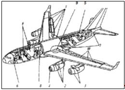
Fig. 2. Use of composite materials
in the airframe of the aircraft Tu-204: 1 - Elements of the wing; 2 - pylon; 3
- nacelle (the bow door); 4-IBD; 5 - gear doors; 6 - wing fairing; 7 - elements
of feathers: keel stabilizer; 8 - nose fairing; 9 - MAT sash; 10 - Cell panel;
11th floor; 12 - monolithic parts
. 3 shows the use of composites in
the airframe far mainline widebody aircraft Il-96-300 (KB them. Ilyushin). The
design of the aircraft has been used a large number of composites (1650 kg),
which reduced his weight to 520 kg. Feature use of composites in the airframe
of the IL-96-300 is that all elements of design are made using hybrid
materials. In thin plating on the surface of carbon-impregnated tapes create
form for single layer process organic tissue, which provides resistance to
erosion and protect the fragile layers of carbon fiber from damage during
operation. In more layers organoplastic loaded structures are uniformly
distributed over the thickness of the skins (25% of total layers organoplastic
number of layers) that provides a higher fracture toughness as compared hybrid
construction with carbon-fiber. In addition, applied additional layers of
fiberglass, carbon fiber, which are corrosive eliminates contact with aluminum
and steel parts. Thus, the reduced complexity of implementation of adjustment
and assembly work in the assembly of parts, since in this case the drilling is
performed by cutting and fiberglass layers, more manufacturable. Much attention
in the production of the IL-96-300 given to the corrosion resistance of
composites.
 . 3. The use of
composite materials in airframe structures IL - 96 - 300: 1 - Elements of the
wing; 2 - pylon; 3 - nacelle; 4 - the air intake; 5 - service hatches; 6 - gear
doors; 7 - wing fairing, side panel; 8 - honeycombs and monolayer paste; 9 -
cell floor; 10 - aft of the wing panel
. 3. The use of
composite materials in airframe structures IL - 96 - 300: 1 - Elements of the
wing; 2 - pylon; 3 - nacelle; 4 - the air intake; 5 - service hatches; 6 - gear
doors; 7 - wing fairing, side panel; 8 - honeycombs and monolayer paste; 9 -
cell floor; 10 - aft of the wing panel
time in the Russian practice of
creating mainline passenger aircraft airframe airplane Il-96-300 composites are
widely used for the elements of the wing, gear doors, pylons, nacelles and
other, as well as honeycomb floors, interior. The design uses composite
materials (mostly hybrid ugleorganoplastiki) based on universal binder EDT-69H
(with the use of epoxy resins KDA. ETF, DP-631U), but not inferior to their
foreign counterparts characteristics. In IL-96-300 were widely adopted
high-strength film adhesives VC-51 and VC-51A (reinforced), which helped to
create highly laminated structural elements, ensuring higher reliability and
weight reduction power airframe.work performed to modify interior materials -
decorative films PDOAZ-25 organita 7TLK, leatherette AIKos, floor material
"Abilene-2»rubberized fabric 51-ST-1H for flexible pipelines and other FCC
allowed to bring them to meet the requirements of "airworthiness life "flammability,
smoke production, toxicity., developed, implemented, and materials science and
technological design and technological solutions for the manufacture of
air-conditioning system components made of fiberglass STP-97KP, bins of
mikrosferotekstolita MCT-7P; in order to reduce the complexity of manufacturing
structures of complex configuration designed knitted filler used in the
construction instead of honeycomb; designed molding thermoplastic PA-610
decorative structural purpose, the technology of color components during their
manufacture by injection molding using a masterbatch pigments; developed a new
flame-retardant multifilament yarn "Togilen»are block the fire for fabrics
and other materials to ensure mass increase efficiency, reliability and
durability, comfort passenger compartments.the basis of the synthesis of
structurally layout and technological solutions composites are increasingly
being used, including the creation of large heavy-duty units in Helicopter KB
them. Kamov. Thus, the weight of the composite structures in a helicopter Ka-26
was 6%, the Ka-27 (Ka-32) - 15%, Ka-126 (Ra-226) - 17%, the Ka-50 - 35%, the
Ka-62 - 55%. Designed by four generations of the rotor blades made of
composites. Currently are manufactured and are in operation blade helicopters
Ka-26 and Ka-27 (Ka-32), Ka-50. Application of composites in helicopters KB
them. Kamov provides: weight reduction by 15...35% increase in resource 1.5...
3 times, increase vitality, reducing labor and manufacturing cycle helicopter
1.5... 3 times., uniform rotor blades of helicopters Mi-17 and Mi-38 made of
composite materials with the planned flight hours 5000 h of material cost and
complexity of manufacturing in mass production have equal performance with
similar production costs of all-metal blades with a flight resource 2500 hrsthe
superior performance properties, qualities (reduced vibration, increased load
capacity of 300 kg, increased survivability and reliability), increase flight
hours for blades made of composites to 5000 h and above, the development of
production of rotor blades made of composites at the Kazan helicopter plant is
economically effective measure for the modernization of the Mi-17 and an
important direction in the development of production of the Mi-38. Compared
with helicopters Mi-8, Mi-17 Mi-38 provides for a further significant increase
in the use of composites in the fuselage, fin, stabilizer, and other elements
of the design of the helicopter.design of the AN-124 "Ruslan»is widely
used polymer-based composite materials and high-strength high-modulus carbon,
glass and organic fillers in excess of their foreign counterparts. (Fig. 4).
European consortium "Airbus Industrie»in the Airbus A380 composite
materials used for engine nacelles, wing skins and tail (Fig. 4). Composite materials,
designs Application of KM used in aircraft An-124 aircraft A 380 "Airbus
Industrie"
 . 4. The use of
composites in the construction of passenger aircraft
. 4. The use of
composites in the construction of passenger aircraft
use of composites in aviation,
especially in military aircraft occurs mainly through the expansion of the
scope of their use in the main parts of the airframe: the tail, wing, fuselage,
helicopter important trend is the use of composites for the production of drive
shafts and blades main and tail rotor. In addition, they are used for the
manufacture of radar fairings, interior panels, ceiling, ducts, fuel tanks,
armor protection for the team and the most vulnerable parts of aircraft and
helicopters, etc., it should be noted that the introduction of composites in aircraft
structures bearing elements, especially heavy civil, at the first stage was
carried out with extreme caution, limited mostly weak and moderate details. The
reason - lack of confidence in the operational reliability of new materials,
related primarily to the limited amount of experimental studies and field
tests. The gradual accumulation of experimental data on the performance
properties of the composites, as well as experience in the development and
operation of various types of composite structures and improvement of their
quality control has led to the fact that to date there is a large number of
aircraft such as the DC-10, "Boeing-727", -737, -747, -757, -767,
A-310, etc., as well as helicopters, «Sikorsky S-76», «Sikorsky SH-53D» and others,
which designs, including vital important, composites have been used.. 5 gives
examples of the use of composites for aircraft "Boeing 767". Total
weight of the aggregates composites pas airplane, "Boeing-767" is
1534.5 kg, which reduced the weight of the aircraft by 813 kg. Another example
- MD -100 aircraft company "McDonnell Douglas" in the construction of
which was used around 6950 kg of composite materials.
 . 5. The scheme of
composite materials in the construction of a Boeing-767: 1 - wall spar; 2 -
fixed rear panel; 3 - spoiler; 4 - aileron internal; 5 - ending keel; 6 -
Rudder: 3 - elevator; 9 - facing the cargo compartment; 10 - wing fairing; 11 -
fairing exhaust system, flaps; 12-trim upper and lower wing stringers: 13 -
external aileron; 14 - Cabin gondola
. 5. The scheme of
composite materials in the construction of a Boeing-767: 1 - wall spar; 2 -
fixed rear panel; 3 - spoiler; 4 - aileron internal; 5 - ending keel; 6 -
Rudder: 3 - elevator; 9 - facing the cargo compartment; 10 - wing fairing; 11 -
fairing exhaust system, flaps; 12-trim upper and lower wing stringers: 13 -
external aileron; 14 - Cabin gondola
most cases the replacement of metal
alloys in detail for composites has resulted not only to reduce the structural
mass (up to 20-40% as compared with metal analogues), but also to reduce their
costs.body parts plating engineswalled body parts easy load aircraft engines
are the most promising in terms of use of polymeric composite materials. Easy
access for periodic visual inspection, diagnosis, and replace them if
necessary, ensure reliable operation during the operation of the propulsion
system. In a composite performance of body parts have a mass of 20...5% less
than metal counterparts. Currently in mass production are the following
components of the PS-90A: with sound-absorbing casing nozzle contour nozzle
fairing and rear cowl reversing device that reduce engine weight by 21kg.
During the implementation phase and experienced mining are: aperture, body
suspension, power building, housing the valves, external fairing reversing
device, sound-absorbing panel with circuit inside the housing 1, cowl, hood,
housing, providing additional engine weight reduction by 39 kg. At the design
stage are: the fan housing, paddle rectifiable grille reversing device, a power
strip with a planned win by weight to 63 kg., the total weight reduction PS-90A
engine when using composite parts is about 123 kg. This leads to an increase in
payload for medium-haul aircraft TU-204, equipped with two PS-90A engines to
246 kg and for haul aircraft type IL-96-300 four-engine 492 kg. The obvious advantage
of composites has led to what is now creating a new PS-90A12 at the design
stage requirements laid perform a number of body parts from composite
materials. Molding composite body parts is carried out by hand lay on the
mandrel variously oriented layers of glass and karboprepreg. Most of the parts
are performed entirely from composites, although some constructive solutions
provides for the use of metal flanges that can be subsequently replaced with
flanges made of composite materials as mining past.the general case, the body
parts of aircraft engine complex system of concentrated and distributed loads,
the main ones are: the internal pressure, tensile load of gas forces and
resultant inertial forces applied at the center of mass construction. In addition,
the individual components may be exposed to excessive external pressure, the
incident exposed the outer flow and compressive forces arising when assembling
aircraft engine casing design. Most loaded elements are parts with flange
mountings that are considered structural variants made of the same materials as
the items themselves and make them one. According to the requirements
specification flanges must ensure secure mounting in the temperature range from
-60°C to 100°C under the action of inertial forces with overdrive 5733g and
vibration loads with a frequency of 5 Hz to 200 Hz, the amplitude of vibration
acceleration to 3,5 g, and have the resources 25 000 hours of work over a
period of 10 years. Currently being developed methods of calculating composite
flanges for strength, allowing to predict resource body parts in which they are
used.
2.
Technological part
2.1 Repair process design
polymeric composite materialsin a
production environment is to restore the exiting characteristics of the
aggregates. To provide high quality repair need to perform complex preparatory
work ensured opting temperature and humidity conditions in the room (the
temperature below +18°C, relative humidity up to 75%).preparation for the
elimination of a particular defect should:the damage zone;the boundary of
damage;the thickness of the skin, its composition and the type of aggregate in
the repair area;appropriate working methods, equipment, tooling, ma-ones;the
rules of work safety.carrying out repair work area must be cleared of
contamination at 350 mm from the edge all around the defect. Installing patches
on the repaired zone can be performed on two schemes: pasting pre-manufactured
lennyh forming patches and patches of prepreg layers in specially cut.. recess
in the hull with partial replacement (if necessary) the aggregate. The second
scheme is more desirable because it allows you to recover up to 91% of the
original strength. [14]determine the suitability of aggregates from PC to
operate all available on these defects, as well as repairs made must be applied
to the circuit units, indicating the approximate contour defect, its type,
size, and distance to the edge of the unit. Scheme retained for the life of the
units.process of repair of units begins with the implementation operation
markup defective areas, which is carried out with graphite pencils, colored
bars on LCP. Next, the layout of the repaired area of the unit, which is
limited to smooth lines with a minimum radius of curvature of 10 mm. The
contour of the cut portion is spaced at least 8.10 mm from damage. Conducting
further processing steps depends on the type of defect, so we will consider
perform repairs all types of defects according to the classification [14] as
shown in Table. 1
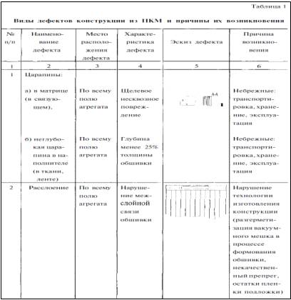

2.2 Removing scratches
scratches in the matrix, which do
not affect the filler produced by applying an adhesive trowel VC-9 (or VC-27)
on the pre-treated with fine sandpaper defective portion width of 5 mm to the
full depth scratches. On the area of repair is rolled film of Teflon, set plate
thickness 0.3-0.5 mm, and the load carried by the adhesive curing regimes
listed in Table 2. Eliminating shallow scratches (depth less than 25% of the
planking thickness) according to the following technologies:from sanding paint
repair zones with-According markup;with fine sandpaper section width of 10-15
mm;scratch length at half its depth;with sandpaper scratch the entire depth
with a width about 5 mm and 25-30 mm zone circle scratches. After a clean, dry
brush the dust from the defective area;and glued (create form) 1-2 layers of prepreg
(You can use fiberglass impregnated with glue VC-9 or VC-27 without filler),
depending on the depth of the scratch. Prepreg overlap in both directions from
scratch at least 60 mm;form are create plies of prepreg technology will be
discussed later when describing the process of repair peeling skin from
honeycomb holes and partial replacement of units with plating.deep scratches
made similarly eliminate friction communities.
.3 Eliminating bundles
process of removing skin bundles
depends on place of its discovery. Bundle can be on the perimeter or on the
field plating.detection of the bundle perimeter trim it eliminates after-as
follows. Originally cleared defect from the old binder sandpaper or a thin
plate with notches. Glue are spew or binder with a syringe (if necessary can be
heated to a temperature of 40-50°C), tightly compressed area repair manually.
Removing excess binder or adhesive cloth soaked in acetone, going technological
package of release film (PTFE, polypropylene), heater, thermocouple, tsulagi,
heat insulator. On the opposite side contains (a face) and sponge rubber on top
of it a metal plate. Installed with a calibrated tightening clamps and
performed the appropriate mode of curing the binder or glue.of bundles in the
field of skin-drills openings in the repair area (Fig. 6). In a nut-holes are
eyelets previously degreased in acetone and gasoline. Drying after treatment
each solvent for at least 15 min at room temperature. Before screw and piston
assembly daubed glue (eg VC-9). Excess adhesive removed carefully. The length
of the screw must be less than the height for the cell-filler in the repair
area. Through the holes in the nut - Pistone zashpritsovyvaetsya glue and set
screw. Conducted mode adhesive curing.
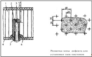
Figure 6. Repair installation
bundles with nuts-pistons
- the repaired unit; 2 - glue
zashpritsovanny zone in repair;
- screw installed in the nut-cap; 4
- Exfoliate trim;
- nut-cap; 6 - bundle
.4 Eliminating delaminations
sandwich constructions from
composite honeycomb possible detachment following:skin from the honeycomb;of
honeycomb from the frame;skin from the carcass.methods to address these
different scalings from each other, so we consider separately each kind of peeling.
But common process step prior to any type of decoration, is the removal of
moisture from the cellular structures, as will be discussed nor-same.
.5 Moisture removal of cell
structures
accumulates in the field unit,
wherein there are mechanical-damage firmed, as well as in areas near the sites
of assembly and linkage joints with ribs style Farmhouse. After the control for
the presence of moisture in the aggregate, in the zones where it has been
detected, and also in areas of mechanical damages and delamination of the
complex of operations to remove moisture. Technological methods and equipment
are slightly different from each other no matter what zone removes moisture
(Cabin - honeycomb; skeleton - Honeycomb). Moisture removal zone "frame -
honeycomb»cracked technological holes in parts of the framework and the
presence of the anchor or anchor retaining nuts in the frame through their
holes pierced or drilled foamable adhesive composition in the cells at a depth
of not more than 10 mm (hole diameter is 2-2.5 mm). Moisture removal zone
«Cabin - honeycomb» reams holes 3.6 s 3.8 mm staggered pitch of 60 mm.
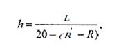
Technological holes and anchor nuts installed fittings (Fig. 7) for connection
to a vacuum system. Connections to the unit are fixed by using a sealant (VIKSINT
Y-2-28, VGO-1 etc.) or rubber O-rings. Connections may be made of transparent
materials for visual observation of the process of removing moisture.unit is
placed in the drainage layer of the fabric and was collected by vacuum bag
(Fig. 8). Assembled technology package is placed in a heat chamber or bottom
heating system installed. Created under the bag, in the defective area,
depression 0 OZMPa (0.3 kgf / cm) and temperature rises in the area Repair to
(90 ± 5)°C at a rate of 2 degrees per minute. Maintained under discharge unit
and heating for 6...8 h, removing the vacuum unit is cooled to 40°C.
Re-verified by the unit for the presence of moisture. When re-evaporation of
moisture detection moisture persists, and in its absence you can start to repair
the unit.
 7. Installation
fittings in the frame and trim parts to remove Moisture: a) a frame assembly;
b) in the casing
7. Installation
fittings in the frame and trim parts to remove Moisture: a) a frame assembly;
b) in the casing
- socket to remove moisture; 2 -
rubber gasket; 3 - wall spar; 4 - foamable composition; 5 - honeycomb; 6 -
anchor nut; 7 - axis; 8 - sealant; 9 - a nut; 10 - sheathing with a hole
 . 8. Shema connect
vacuum pump to remove moisture and
. 8. Shema connect
vacuum pump to remove moisture and
- connection to a vacuum tube (or
ejector) pump; 2 - standard elements (cross, tee) 3 - fitting attached to the
opening in the defective area; 4 - vacuum bag; 5 - drainage layer; 6 - repaired
unit; 7 - tube for sucking water vapor; 8 - fitting, mounted on a vacuum bag; 9
- a tube that can be connected, converging to the vacuum pump
2.6 Troubleshooting peeling
skin from honeycomb
of honeycomb paneling on units
without testing oping acoustic and vibration loads and without special
destination, eliminating zashpritsovkoy glue defect installing caps made of
aluminum alloy (if sheathing of fiberglass) or titanium (Fig. 9).zashpritsovku
glue and install plugs drilled staggered at 20 mm, if the defect is 40 mm
wider. Drilling depth of 3-5 mm. After drilling is removed from the treatment
zone vacuuming dust and shavings
 9. Repair peeling
with installing plugs type "Screw": 1 - the repaired unit; 2 -
adhesive in the area zashpritsovanny repair; 3 - stub; 4 - the opening in the
wall of cells for wicking glue
9. Repair peeling
with installing plugs type "Screw": 1 - the repaired unit; 2 -
adhesive in the area zashpritsovanny repair; 3 - stub; 4 - the opening in the
wall of cells for wicking glue
repairing units in the zone of
possible contamination from heated gases from engine, zashpritsovka made using
adhesives having improved heat resistance.into the aircraft parking conditions
can only be installed bottom surface, as their installation is carried out
simultaneously with zashpritsevkoy glue defect. If necessary, install the plugs
on the upper surfaces of the unit it must be removed from the aircraft. To
ensure uniform and complete distribution of glue over the entire surface of the
defect between the skin and honeycomb core runs drenazhirovanie wall honeycomb
special device (Fig. 10). The openings in the walls of cells should have a
circular shape and positioned at a distance of 0.5... 1.5 mm from the drilled
casing.
 10. Drainage scheme
honeycomb before zashpritsovkoy glue: 1 - a device for drenazhirovaniya; 2 -
honeycomb; 3 - sheathing repaired unit; 4 - hole; 5 - Drainage channels in
Honeycomb
10. Drainage scheme
honeycomb before zashpritsovkoy glue: 1 - a device for drenazhirovaniya; 2 -
honeycomb; 3 - sheathing repaired unit; 4 - hole; 5 - Drainage channels in
Honeycomb
to install plug in unit (shortened
degreased) produced zashpritsovka glue into the hole in the unit. For repair
mainly used pasty adhesives type VC-9, VC-27. They have high viscosity, and
discharge them in a special unit be used syringes. The largest application
found a syringe with a screw rod, providing pumping cold pasty adhesives (Fig.
11). It is filled with freshly prepared adhesive, then the tip of a syringe
inserted into the hole defects glue squeezed by turning the handle.
Zashpritsovka glue stops when a sharp increase in pressure (force) extrusion or
when the glue from adjacent holes. After work syringe should be carefully
washed from the glue residue.after zashpritsovki placed in the hole plug, not
up-blowing straight. Adhesive flash removed c / b cloth soaked in acetone.
 11. Syringe with a
screw rod: 1 - the handle; 2 - screw rod; 3 - union nut; 4 - the case syringe;
5 - piston; 6 - tip
11. Syringe with a
screw rod: 1 - the handle; 2 - screw rod; 3 - union nut; 4 - the case syringe;
5 - piston; 6 - tip
caps reinforced adhesive tape and
adhesive curing mode is provided. If necessary, heating the repair area is
placed on the heater bag and the process is going to the air bag to provide a
pressure of 0.05... 0.1 MPa (0.5 L.., 0 kgf / cm), and curing of the adhesive
is carried out according to modes specified in Table 2. Processing methods for
heating repair zones are discussed in "heating repair zones."the
curing of the adhesive regime visually monitored installation quality plugs.
Availability bundles and controlled delamination flaw or tapping.of honeycomb
paneling on special units destination (units of the wing, empennage assemblies,
gear doors, etc.) must be repaired by removing a plating zone defect with
subsequent molding of the prepregs and adhesive film, and if necessary (eg, the
presence of corrosion damage of metal honeycomb or damage) perform the replacement
honeycomb. Technological process of restoring the defective skin is complex and
responsible, so it will be discussed in next section.
2.7 Restoring skin prepreg
while gluing it to Honeycomb
performing partitioning defective
area on the unit produced Remove defective plating. Removing the defective skin
is made using carbide end mills with a diameter of 5-g 12 mm and above by
lilnyh cars mod. SM21-1000-9, as well as diamond wheels, installed lennyh on
special pneumatic cutting machines. Device for machining equipped with built-in
vacuum cleaners RMB using ejector type devices operating on compressed air and
creating vacuum of about 0.03 mPa for removing dust in the process.working with
the cutting tool systematically, at least 1 time in 20 minutes of continuous
operation, verified tool sharpening. Blunting of the cutting edges - is not
more than 0.15 mm. On the surface of the fillet radius edge may be formed which
are removed by abrasive grinding wheels type PP bunch "K»- ceramic, grain
50.40.obtain the desired fillet radius selected following the appropriate
diameter. During work on the circle can build-up of dark color
("salting"), which is removed by abrasive cleaning bars.the
preparation of diamond tools for work performed his autopsy diamond grains on
the cutting surface by etching in 10% aqueous ferric chloride solution for
20-25 minutes or performed an autopsy diamond grinding grain bars type BKV, BP
on keramicheskih bundles with silicon carbide abrasive grain green 63C, grain
nistostyu 16 cm hardness at working speed.ensure a high connection strength
restorable plating thickness exceeding 0.4 mm performed bevel angle 1-3° it
around the perimeter. Tenderloin bevels in the skin is made using pneumatic
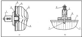
machines and abrasive wheels (Fig. 12). To ensure a given azimuth angle on the
surface strengthened Pneumatic clamps of a soft material, the thickness of
which is determined by the formula:
h - thickness of the clamp;-
distance from the end of the abrasive wheel to clamp;- radius of the circle
abrasive wheel;- radius of the circumference of the body Pneumatic.
 12. Ensuring a
given azimuth angle and cover: 1 - pnevmomashinka; 2 - Handle trim; 3 -
additional emphasis; 4 - grinding wheel; 5 - inner edge of the cut in the skin
12. Ensuring a
given azimuth angle and cover: 1 - pnevmomashinka; 2 - Handle trim; 3 -
additional emphasis; 4 - grinding wheel; 5 - inner edge of the cut in the skin
the bevel is not allowed offset from
the inner edgeholes in the hull. For more accurate processing bevels desirable
surface drill strengthen more stops.removal of the defective skin condition is
checked for cell-filler. Special attention is paid to the presence of traces of
corrosion damage of aluminum honeycomb, no damage ends faces of honeycomb
cells, breaks in cellular docking sites for-filler, etc. For non-compliance
requirements for cell zapolnitelyu5ego removed. To do this, cut out the damaged
section with a knife honeycomb, cutting line as possible should be a simple
form we. When using metallic honeycomb Packer on the line side surface in the
recess sotobloka according to Figure 13.
 13. Stitching faces
metallic honeycomb: 1-unit repaired; 2-line; 3 - plate
13. Stitching faces
metallic honeycomb: 1-unit repaired; 2-line; 3 - plate
from the surface opposite the
remains of plating cell filler, foaming and film adhesives careful not to
damage trim.work on removal of moisture (whether there was a time-sealing
machine), because in the non-metallic parts in the process of exploitation ed
out incandescent or medical reflectors. The distance from the heating device to
repair zones selected for the requirement of a surface temperature of 60-70°C
and the heating time is calculated from the rate of 1 hour for each 0.3 mm
thick cladding material.work to replace the damaged honeycomb lie in the
selection and fitting of honeycomb and its subsequent gluing the defective
area. Selection honeycomb depends of what material it is made of (aluminum
fillers, PSP or cell MTP).replacing the metal honeycomb increases the size of
the workpiece on the amount of 5-8 mm podmyataya, and for non-metallic
honeycomb podmyatie not performed, and the size of the workpiece corresponds
strictly circuit remote site. Also, take into account the direction in which
the sheets of foil, paper or glass in sotobloke repaired. At repair units
height wedge insert cells taken 1-2 mm is greater than the height of the
removed portion (for subsequent fitting), and to panels fixed height height
equal to the height of cellular insert removed trolled or more aggregate
thickness skin removed. Honeycomb CAP and MTP are dried before use at 110°C for
1 hour.fitting insert cell block is performed degreasing surfaces to be bonded,
and only degreased metal surface and the honeycomb core of aluminum alloy.
Degreasingis made in a special bath of pure stiff hair brush, dipped in
gasoline, then in acetone, and drying the solvent after each treatment at least
15 minutes. Degreased and also on the lateral surface of the metal honeycomb
core unit repaired, glued to insert cells.is cut and glue film is rolled into
the zone of repair a face by removing the original protective paper, and after
stitching protective ing a polyethylene film and the side surface of honeycomb
inserting the expandable adhesive film is rolled UTC-3. Setting
sotozapolnitelya insertion into the defective area is warmed through the
honeycomb core with the adhesive film using the reflector to a temperature of
50-60°C, and the maximum cell pressed into the adhesive by pressing the hand.
Not allowed aggregate crushing insert. Fixed insert tape, placing it on the
paneling crosswise. If the unit has a complex circuit or significant size of
the defect, it is desirable to pre-glued honeycomb, check his protruding above
the surface of the unit, and if it observed, then remove pursuant to Section
7.13. After preparatory work on gluing and fitting insertion sotobloka can
proceed to making patches of individual layers of the prepreg. For the
manufacture of the patch used as a pre-fabricated prepreg binder and an
adhesive prepreg made of film adhesives, or hot curing adhesives, cold-curing
paste. Producing prepregs tie-treated in special courses on manufacturing
technology of PCM, and we consider the production of prepreg adhesives directly
on-site repairs. For the manufacture of prepregs used dry carbon tape, glass
and organotkani, transcribed film adhesives VC-36, VC-41 or VC-51 with a ratio
of tape layers (Tissue) and the adhesive film 2-1. The resulting prepreg is
laid out on the repaired unit through a layer of adhesive film and molded
plastics for curing mode (see Table 2). Modes curing prepreg curing regimes
correspond adhesives used to manufacture them. Perhaps obtain a prepreg by hot
melt adhesive on the corresponding dry cloth or tape, and tape molding,
appropriate tissue glue, by laying cloth tape and an adhesive film between the
film layers (Polypropylene or PTFE). Crimping mode:- 1.0... 2.0 MPa;- 10
minutes;- 80°C (adhesives VC-41, VC - 51) or 100°C (adhesive VC-36).the same
approximate binder content in the prepreg is 35-40% by weight.the manufacture
of a cold-curing prepreg layer fabric, flax, you laid on the release film
(polyethylene). On the tape or fabric is applied to a freshly prepared
non-metallic adhesive to a spatula until the filler is impregnated with glue by
a release substrate.of the individual layers of the prepreg manufactured at the
site of repair, consists of two parts: internal and external patches patches.
Internal patch is circular or oval and designed to align in-podlitso plating
unit in the repair area. External patch as a right or an elongated octagon,
complementing internal, designed for operation under load filler fibers plating
unit. Overlap external patch to the inner is 30 to 350 mm depending on the
magnitude of loading unit and repair zones, while providing a smooth outer
layers gathering patches steps 5-15 mm. Cutting blanks patches (internal and
external) are produced by Pattern of thick paper. On Pattern paper cut layers
of prepreg patches. Protective layers of prepreg are removed immediately before
laying prepreg. The number of layers is calculated by internal patch formula:
where n - the number of plies of
prepreg;
oS-skin thickness;
i - monolayer thickness of fabric or
tape used to repair (Excluding the thickness of the adhesive when the adhesive
prepreg is used).layer prepreg should be different from the previous one by an
amount that takes into account the presence of the recess in the casing of the
bevel. Assembling patches separately on a release film, heat resistance of the
film should correspond to the temperature curing adhesive used or
prepreg.diagram and install patches from prepreg layers is shown in Figure 11.
Times-measures the lower workpiece is not less than 2.5 mm greater than the
smallest size of the holes in the casing repaired.overlapping plies of prepreg
is calculated by the formula:

b - the value of the overlap;
- chamfer length recess in the
casing;- the number of layers forming the inner patch.direction of the warp
threads of the filler is determined by drawing on the aggregation, and in the
absence of data is kept symmetrical layout, for example, 0°, 90°, ± 45°, +45°,
90°, 0°, etc.0° along the spar or along the length of the unit.
 . 15. Scheme build
and install patches: 1 - the repaired unit; 2 - insert sotobloka; 3 -
expandable adhesive; 4 - layers of inner patches (seal); 5 - reinforced
adhesive film; 6 - outer layers of the patch; 7 - film adhesive
. 15. Scheme build
and install patches: 1 - the repaired unit; 2 - insert sotobloka; 3 -
expandable adhesive; 4 - layers of inner patches (seal); 5 - reinforced
adhesive film; 6 - outer layers of the patch; 7 - film adhesive
installing the patch to repair zone
contains film adhesive compatible with the binder, which is impregnated prepreg
(eg, glue VC-51 film and binder EDT 69H) used for the manufacture of the patch.
After assembling and manufacturing process is carried out patches curing
patches and gluing them to the honeycomb core at a temperature and a pressure.
Existing technology
General - equipment and tools for
repairs
A. Refer
to the following figures for lists of tools and equipment. Miscellaneous
equipment table 2.1-2.5
general, hand tools table 2.6-2.9 general.
B. This
section lists the equipment and hand tools used when making repairs and also
lists sources of supply. The purpose of this list is to provide information
pertaining to item description and use.
C. Some
of the procedures in this manual identify tools or equipment. You can use
alternative tools that are equivalent unless the procedure tells you the
specified tool or equipment item is mandatory. If you use alternative tools or
equipment, make sure they give the same results and are as safe to the parts
and personnel as the tools or equipment specified in the procedure.
Table
2.1
|
Tool
|
Manufacturer's designation
|
Manufacturer
|
Remarks
|
|
Cleaner, vacuum
(B)
|
Industrial-type model#apn4423
(tornado); use a 556AL barrel as a dust receiver
|
Breuer/tornado corp. 7401 w.
Lawrence ave. Chicago, IL60656
|
Clean up sanding dust and debris
|
|
Containers, 1 liter beaker-type,
polyethylene
|
#13915-679
sherwood
or
Equiv
|
V.W.R. Scientific 355 treck drive
Seattle, wa98188
|
Mixing resins and potting
compounds
|
|
Containers, safety,
foot-lever-type
|
Metal, eagle 906-fl or equiv
|
V.W.R. Scientific 355 treck drive
seattle, wa98188
|
Holding used clothes with toxic
materials
|
|
Cork sheet
|
0.125-in
|
Commercial - any
source
|
|
|
Caul plate
|
Fabricate locally using0.016
aluminum sheet
|
|
Use to distribute pressure over
areas of a repair
|
|
Countersink, microstop, 100°
adjust able drive
|
#6300-large, #6400-small,
|
Mc master-carr P.O. Box 740100
Atlanta, ga30374-0100 www.mcmaster.com
<http://WWW.MCMASTER.COM>Countersinking holes for Rivets, screws, or
bolts
|
|
|
Cutter, honeycomb, valve stem
type, two-piece
|
30-030-1
holder (D) 30-030-2 cutter
|
Onsrud cutter mfg co. 800 liberty
drive P.o.box 550
|
Aluminum honeycomb cutter
|
|
Cutter, honeycomb, valve stem type
one-piece
|
31-010 0.50 dia(C) 31-015 0.75
dia(C) 31-020 1.0 dia(C) 31-025 1.5 dia(D) 31-030 2.0 dia(D)
|
Libertyville, il60048 or any other
commercial source
|
Aluminum honeycomb cutter
|
|
Drill motor
(B)
|
15c
1489
or
equivalent
|
Aero industrial tool 482 east
meadow ave. e. meadow, ny11554
|
Conventional drilling, sanding, or
circular sawing
|
|
Pneumatic, ¼-in chuck
model #3008-0 or equivalent
|
Chicago pneumatic 1800 overview
dr. rockhill, sc29730
|
|
|
Drill motor, 90° Angle
|
Pneumatic, variable speed, model
#1ol-1201вor
equivalent
|
Aero industrial tool 482 east
meadow ave. e. meadow, ny11554
|
Conventional drilling, sanding, or
circular sawing
|
|
Gauge, air pressure
|
0 to 100 psi, model j4654 or
equivalent
|
Marsh distributor P.O. box 361
antioch, il60002
|
To indicate air line pressure
|
|
Gauge, vacuum
|
|
Marsh distributor P.O. box 361
Antioch, IL 60002
|
To indicate vacuum line pressure
|
|
Gloves, cotton
|
|
Mc master-carrp.o.box 740100
Atlanta, GA30374-0100 www.mcmaster.com <http://WWW.MCMASTER.COM>Use for
handling cleaned parts or adhesives
|
|
|
Gloves, insulating
|
Heat insulating
|
Any source
|
Use for handling hot parts
|
|
Heater assembly
(B)
|
Hot air, bf-400-10, or equivalent
|
Engineered air systems 1270 n.
price rd. St. Louis, mo63132
|
Hot air blower to duct air to area
being cured
|
Table
2.2
Miscellaneous equipment
|
Tool
|
Manufacturer's
designation
|
Manufacturer
|
Remarks
|
|
Air-blast gun
|
Vacu-blast JR., #41303 or
equivalent
|
Vacu-blast Woodson house Ajax
avenue slough Berkshire, SL1 4DS England -or-P.O. box 286, Herington, Kansas
67449
|
Clean metal surfaces
|
|
Aspirator, vacuum
|
Vacuum model TD-260 or Equivalent
|
Air-vac engineering P.O. box 215,
30 progress ave Seymour CT 06483, Airtronics 1940 124th ave ne bldg. A-107
Bellevue, WA 98005
|
Converts air pressure to vacuum
|
|
Bags, pressure
|
10-LB sand or shot bags
|
Commercial-any source
|
Use as a substitute pressure
medium
|
|
Blanket, heating
|
5 watts/in2 minimum
|
Atacs products, inc. 14040
interurban aves Tukwila, WA98168 Heatcon composite systems600 andover park
Eseattle, WA98188 -or-Unit 8, EdisonRD, ST. Ives, Huntingdon, Cambridge PE17
4LZ England GMI 9 rue buffault 75009 Paris, France -or-GMI/emptech, 5957
Glendale drive Chilliwack, b.c.,, Canada V2R 3A5 JR technology LTD. 81 north
end, meldreth Royston, herts, England SG86NU Pyrometric service corp. 1312 s.
96TH ST Seattle, WA98108-5010 Tayco engineering, inc. 10874 hope st P.O. Box
6034 Cypress, CA90630 Wichitech industries, inc. Oakland center, 8990 RT. 108
Columbia, md 21045
|
To provide heat for curing
adhesive
|
Table
2.3
Miscellaneous equipment
|
Tool
|
Manufacturer's
designation
|
Manufacturer
|
Remarks
|
|
Heater, air
(B)
|
1000 to 2000 watts, model HGS
50110j
|
Master appliance corp. 2420 18th
st. Racine, wi53403
|
For heat-tacking adhesives,
heat-drying honeycomb core or assemblies, warming compounds and/or resins
|
|
Alternate
|
Ideal industries, inc.1006 park
avenue sycamore, il60178
|
|
|
Lamp, heating
|
250 to 300 watts, explosionproof,
tungsten or quartz tube
|
Mc master-carr P.O. Box 740100
Atlanta, ga30374-0100 www.mcmaster.com
<http://WWW.MCMASTER.COM>Low-temperature curing of adhesives, potting
compounds, or resins
|
|
|
Lamp, heating
assembly
|
25 or 40/4 #375g30 or
Equivalent
|
Deltrol controls corp. 2740 so.
20th st. Milwaukee, wi53215
|
Low-temperature curing of
adhesives, potting compounds, or resins
|
|
Mat, fiberglass
|
2 OZ fiberglass or 7500
|
Ren plastics 5656 s. Cedar st.
Lansing, mi 48909 Dexter corp. (hysol products) one dexter drive seabrook,
nh03874
|
Can be used for laminated tooling,
fiberglass bleeder cloth, insulation material, or a substitute for osnaburg
bleeder cloth
|
|
Tooling mat
|
|
|
|
Motor assembly,
Pneumatic
|
Arbor saw/motor
|
Aero industrial tool 482 east
meadow ave. E. Meadow, ny11554
|
To cut away damaged material
|
|
Multitester
|
Low current, low ohm,
kelvin-bridge-type
|
Commercial - any source
|
Taking electronic measurements
|
|
Peening tool, power
(B)
|
1/4-in. Stem (drill rod), Slot end
for flapper strip Mil-b-1170, type ii, class e, style 1
|
|
Use for shot peening requirements
|
|
Power supply, dc
|
Regal line model R2518 unfiltered
bench model r series dc or equiv.
|
|
Use as power source for phosphoric
acid anodizing
|
|
Recorder, temperature, 24-point,
automatic chart-type
|
Model #15306836-24
|
Honeywell
|
Measuring temperature at the
adhesive cure line by thermo couples; 1 through 24 points available
|
|
Recorder, temperature, 1-point,
individual printout, roller chart
|
Model #122 115-volt,
60-cycle
|
Gulton graphic Instrument 1900 s.
Country tr. E. Greenwich, RI 02818
|
Measuring one thermocouple on a
line chart
|
|
Regulator, air
pressure
|
0 to 125 psi, model 11-002-025 or
equivalent
|
С.A.
Norgren co. 5400 s. Deleware ST. Littleton, co 80120
|
Measure and regulate air pressure
|
|
Regulator, vacuum
|
0- to 30-inch hg, or Equivalent
|
Mc master-carr P.O. box 740100
atlanta, ga 30374-0100 www.mcmaster.com
<http://WWW.MCMASTER.COM>Measuring vacuum at the assembly
|
|
Table
2.4
Miscellaneous equipment
|
Tool
|
Manufacturer's
designation
|
Manufacturer
|
Remarks
|
|
Safety face shield
|
Tru-safe #199-1 or safeline#6799
<10 by 18-1/4) or equiv
|
Commercial - any source
|
For face and eye protection
|
|
Safety face shield
Holder
|
Rice head shield #707 Or
equivalent
|
|
Holds replaceable face shield
|
|
Safety glasses
|
5944d smoke clear lenses or
equivalent
|
H.l. Boutonco. Inc. Buzzard bay,
ma 02532 Mc master-carr P.O. box 740100 Atlanta, GA30374-0100
www.mcmaster.com <http://WWW.MCMASTER.COM>For eye protection
|
|
|
Scale, balance
|
1.0 gram accuracy,
multiple
models
|
Mettler 1900 Polaris pkwy
Columbus, oh 43240 or Ohaus corporation 29 Hanoverrd Florham park, nj07932
|
Weighing compounds and resin
mixtures
|
|
Sealant gun
|
Air-operated or equivalent glue
gun
|
Mc master-carr P.O. Box 740100
Atlanta, ga30374-0100 www.mcmaster.com
<http://WWW.MCMASTER.COM>Dispensing of fillers and sealants
|
|
|
Shaver, micro-rivet-Head
|
Model 2t-405, adjustable, or
equivalent
|
Advanced air tool co.,Inc.131
AllenBlvd. Farmingdale, ny11735-5616
|
Shave protruding rivet heads
|
|
Sine plate
|
0° to 45° inclination from
horizontal position
|
Brown 8 Sharpe Precision park 200
French town rd. N. Kingstown, ri02852
|
Use with core-slicing equipment
|
|
Spray unit
|
Power unit, atomized W/glass 6 oz
container
|
Precision valve corp. P.O. box 309
Yonkers, ny10702
|
Used to apply small amounts of
liquid primer, adhesive, or resins
|
|
Surface bleeder, surface breather,
and insulation
|
Bms9-3, type d
|
See 51-20-03, fig. 2
|
|
|
Temperature controller console,
portable self-contained (A)(B)
|
|
Atacs products, inc. 14040
interurban ave. S. Tukwila, wa98168
|
Use with heat blankets,
thermocouples, and vacuum unit for application and recording of heat and
pressure
|
|
|
Gmi9 rue
buffault 75009 Paris, France -or-Gmi/emptech 5957 Glendale drive Chilliwack,
b.c., Canada v2r 3a5
|
|
Table
2.5
Miscellaneous equipment
|
Tool
|
Manufacturer's designation
|
Manufacturer
|
Remarks
|
|
|
Heatcon composite systems 600
Andover park e. Seattle, wa98188 Jr technology ltd. 81 north end, Meldreth
Royston, herts, England Sg86nu Pyrometric service corp. 1312 s. 96th st.
Seattle, wa98108-5010 Taycoengineering, inc.10874 hope st. P.O. Box 6034 Cypress,
ca90630 Wichitech industries, Inc.Oakland center 8990 rt. 108 Columbia,
md21045
|
|
|
Transformer,
Portable
(B)
|
Variablecontrol115-volt,
60-cycle
|
|
Use with heating blankets as A
power supply
|
|
Vacuumunit (B)
|
Any unit compatible with
Temperature control console
|
|
Includes vacuum pump and
Transducer
|
|
Vacuumprobe, quickdisconnect
|
Vacu-valve, 401 round Base, 401a
rectangular base
|
Airtech international, Inc. 5700
skylab road huntington beach, ca92647
|
Use for evacuation of air Inside
bag film
|
|
|
|
|
|
composite panel aircraft
3. Special part
invention relates to the repair,
restoration or reconstruction of a composite article having a defect on the
surface or throughout the thickness, which requires repair or eliminated. In
the process of reconstruction or restoration of a composite article comprising
a sponge layer, such as a cellular material having a defect, damaging the
product, and wherein successively) placed on the bottom of the defect by at
least one additional member or material, shape and dimensions of which
correspond to the shape and size of the defect, b) inserted into the defect
replaces the spongy part, g) is placed on the elements in the defect
transferred sequentially stacked, a device such as a textile layer for draining
gases released from the resin during step (d), and a sheath for the
above-mentioned gas outlet forming the rest of the product chamber, sealed
against the outer atmosphere surrounding the defect and the above additional
elements and d) continuing to evacuate the sealed chamber is heated an
additional element. An additional element or a material containing the
above-mentioned continuous or chopped fibers, are mechanically robust,
organized or unorganized, which is placed on the bottom of the defect, either
separately or appropriately in relation to the fibers of the aforementioned
element or the aforementioned material for the first resin placed on the
receiving step d) of the polymeric matrix, wherein said fibers are distributed.
Exchangeable cancellous portion is, for example, a honeycomb material, and b)
placed on the outer portion of the second spongy resin with at least one
element of fabric continuous or chopped fibers. Second resin is applied
separately or as appropriate to the fibers of the above item. A radiation
source which heats the additional element comprises an infrared radiation that
is positioned with respect to the defect so as to irradiate the shell for
discharging the gases released from the polymer matrix and with the proviso
that the above-mentioned radiation source acting on the other side of the
spongy part. The method allows to obtain a monolithic product that does not
separate into components.present invention concerns mainly the product recovery
or reconstruction, particularly composite articles or composite parts or
products or items made of composite material having a defect to be corrected or
eliminated by affecting at least its surface, and even its entire thickness.
More specifically, the invention relates to the restoration or reconstruction
or repair of articles such as defined hereinabove, by placing the
above-mentioned defect in or on the above-mentioned defect, on the one hand the
continuous or chopped fibers, are mechanically robust, organized, for example
in the form of technical or fabric layer or fugitive example, in bulk or in non-woven
form, and, on the other hand, a thermoplastic or a thermoplastic resin or a
structured or structured polymeric material (a resin or mixture of polymers),
in particular a thermosetting or termosshivaemogo, wherein the integer defines
the solid matrix, which are distributed or arranged above the fiber.an example,
the fibers are glass fibers, carbon fibers or Kevlar fibers, the resin is an
epoxy or polyester, or a phenolic, or dimaleimidnuyu resin. These fibers may be
separately placed into the defect from the resin, in this case, the above
fibers are arranged in the above defect, for example in the form of
superimposed layers of fabric, then the fabric weight is injected in liquid
form resin or with a resin in this case Ready-to-drink use a composite material,
such as pre-impregnated material comprising the weave formed by the
above-mentioned fibers and the resin matrix, for example, semi-structured or
unstructured. In all cases, the structure obtained by a defect or a defect, a
so-called monolith or monolithic unit because in the solid state is virtually
impossible to split, for example by peeling, to the aforementioned components,
namely the fiber or fibers, with one hand, and resin, on the other hand.used
herein and in the claims, unless otherwise indicated, the term
"composite»is meant the structure, the article or material formed by
joining heterogeneous materials or several basic components, namely in
particular, fibers and resins interconnected and having a set of properties,
especially mechanical, which does not possess any of the components
individually.used herein, "resin»refers to polymeric materials which, in
essence, can be identified by the term "adhesive»or "glue»such as
structural, it is a curable or thermoplastic polymeric materials. In accordance
with current repair of the domestic aviation company, and more specifically,
the method of implementation, shown in Figure 1 of this document describes a
method for recovery or reconstruction work, eg composite article having a
defect, affecting at least its surface. According to this method: A - a defect
or flaw is placed at least one additional member or material, shape and
dimensions of which correspond to the shape and size of the above-mentioned
defect, wherein the element or material comprises a continuous or chopped
fibers, are mechanically robust, organized or disorganized; for example, the
defect was placed in a superposition of layers of a fabric, connecting
mechanically strong organized fibers; b - in the defect or the defect placed polymeric
material or resin to produce a polymer matrix in which the fibers are
distributed; for example, this polymer material is fed to a defect in a liquid
form under pressure, thereby impregnating the above-mentioned fibers and the
polymer after curing, yielding a solid polymeric matrix material in which the
fibers are distributed; in - on an additional element impregnated polymer
matrix and sequentially one above the other, are placed means for draining the
gases released from the polymeric matrix during the next step (g) and the
degassing membrane, forming with the rest of the article during recovery or
Repair chamber, sealed towards the outside atmosphere surrounding the defect
and the additional element;an example, a device for degassing is a layer of textile
material for gas drainage; r - still evacuating the sealed chamber, an
additional element is heated by a radiation source whose radiation comprises
infrared radiation, placing this source with respect to the aforementioned
defect so as to irradiate the sheath to remove gases released from the
polymeric matrix. The current method of repair process identified before it is
described only for the treatment or repair of massive articles of the same
material, except for any product. On the other hand, today, to repair a
monolithic composite article, for example, in the aviation industry, work as
follows, as shown in Figure 1, which represents a schematic view:
preparing, in particular, by cutting
one or more elements of two or material, shape and dimensions corresponding to
the shape and size of the defect 1a subject to removal or filling; This
material, or the elements connected with each other or superposed on each
other, are themselves a composite material, in the sense that they are
inseparably combined polymer matrix and continuous or chopped fibers, organized
or unorganized, mechanically durable, such as carbon, Kevlar, glass, etc.;
Transferred and placed element or
elements 2, or the thus prepared material into a defect or a defect of the work
piece 1a;
An element 2 and the product 1 is
placed in series on one and the other side surface of the defect and other
ones:
a perforated or non-perforated film
9, non-adhesive with respect to the additional item 2, further processed, e.g.
crosslink kable;
A textile layer 3 to drain through
its peripheral edge 3a of the gases that are released from a polymer matrix
during its processing, for example, its cross-linking;
Film 8, sealed with respect to the
polymer material;
A flexible heating device 10 as a
cover, typically including heating electric resistances are immersed in an
electrically insulating material such as silicone;
Layer 11, the heat insulation
relative to the surrounding environment;
A flexible sheath 4 and for
discharging the gases formed posredstom respective devices 12 (e.g., gaskets)
with the rest of the chamber 5 of the article 1, sealed with respect to ambient
atmosphere; this shell surrounds not only the defect 1a, and the additional
element 2 but also all the superposed elements described before. The shell 4
for discharging gas, a vacuum, e.g., via a pump 13 and a flexible heating
device is connected to the power source 14. Using appropriate controls, in
particular temperature sensors, a heat treatment, for example, a polymeric
matrix is subjected termosshivaniyu when this latter is heat-curable or
crosslinkable polymer. The heat treatment is strictly controlled according to,
inter alia, on the nature of the polymer matrix and the desired mechanical
characteristics.present invention relates to the restoration or reconstruction
of composite articles such as "sandwich", i.e. products having in
their composition a solid layer of sponge, for example a material such as
"honeycomb»of various materials, such as cardboard, impregnated with phenolic
resin, plastic, and metal or a structural foam. This spongy layer is
structurally connected at least on one side, with a monolithic layer such as
defined before, i.e. combining a monoblock polymer matrix and the mechanically
strong fibers distributed in the matrix. Today there is no satisfactory
solution to allow repair or reconstruct composite products such as
"sandwich", particularly when you can only get to the surface of the
above-mentioned products.fact, in order to reconstruct or recover such a product,
for example, the upper surface of an aircraft wing having a sandwich-like
composite structure, defect is first treated to give it a regular or controlled
geometry. Then, the bottom of the treated defect was placed resin or adhesive,
and then an additional element of the sponge material, the sponge-aligned layer
level repaired product, the resin also connecting it to the rest of the sponge
layer; and finally, the monolithic layer to the level of the repaired product
is applied mechanically strong fibers and the polymeric matrix layer for
recovery in the above-mentioned defect. The application of heat and pressure
required in order to connect and bind the set of elements or materials which
fill the defect, and the latter with the rest of the products recovered or reconstructed
provide, performing one or more times with the following operating steps:
At the level of product in the
repaired defect and successively placed one on top of another layer of the
textile material to drain through its peripheral edge gases released from the
polymeric matrix during the next step, the flexible heating means in the form
of a cover, which includes electrical heating resistance immersed in the
electrically material, such as silicone, and a shell for discharging the
aforementioned gases, forming with the remaining part of the product chamber
sealed with respect to ambient atmosphere surrounding the defect and the
elements and materials that are placed therein;
Still evacuating the sealed chamber
through the flexible heating device is heated further elements and materials
that cause or initiate the crosslinking of the polymer matrix in the case of a
thermosetting resin. In the case of composite products having inaccessible
surface such as inner, heat-treating the resin on the bottom of the defect does
not exist other solutions than:
Strongly heated by the heating
device of the flexible core defect to try to reach the inner surface of the
heat; but such a strong heat, besides the fact that it is not very effective,
capable of repairing damage to the outer surface of the product; or in case it
is necessary to cool the flexible heating device or along the periphery of the
product;
Remove the product to gain access to
its interior surface, the repaired or replaced by a product that in some cases
it is impossible or in any case is economically disadvantageous. In the first
case, when the temperature cycle do not provide required for crosslinking the
resin in the depth of the defect, the latter does not occur or is deficient, so
that the entire reconstruction of the product is a compromise. Known
reconstruction or restoration method of a composite article comprising a sponge
layer, such as a cellular material having a defect, damaging the product, and
wherein successively) placed on the bottom of the defect by at least one
additional member or material, shape and dimensions of which correspond to the
shape and size of the defect, b) inserted into the defect replaces the spongy
part, g) is placed on the elements in the defect transferred sequentially
stacked, a device, such as a textile layer for draining gases released from the
resin during step (d), and a sheath retraction for the above gases, forming
with the remaining part of the product chamber, sealed against the outer
atmosphere surrounding the defect and the above additional elements and d)
continuing to evacuate the sealed chamber is heated an additional element.,
this method also provides for efficient recovery of the composite article due
to the fact that crosslinking does not occur due to the depth of the defect
resin. Object of the present invention is to find solutions for the
reconstruction or restoration of composite products such as sandwich. According
to the present invention, beyond all expectation, found that the use of a
radiation source emitting infrared radiation disposed in relation to the
treated defect so as to irradiate the shell for discharging the gases released
from the polymer matrix allows the heat on the other side of the sponge layer
sandwich composite articles with respect to the aforementioned shell degassing,
and this despite the thermal resistance, normally exerted all spongy
layer.problem is solved due to the fact that in the process of restoration or
reconstruction of a composite article comprising a sponge layer, such as a
cellular material having a defect, damaging the product, and wherein
successively) placed on the bottom of the defect by at least one additional
member or material, shape and whose dimensions correspond to the shape and size
of the defect, b) inserted into the defect replaces the spongy part, g) is
placed on the elements in the defect transferred sequentially stacked, a device
such as a textile layer for draining gases released from the resin during step
(d), and a sheath retraction for the aforementioned gases, forming with the
remaining part of the product chamber, sealed against the outer atmosphere
surrounding the defect and the above additional elements and d) continuing to
evacuate the sealed chamber is heated an additional element or an additional
element of the aforementioned material containing continuous or cut the fibers
are mechanically strong, organized or unorganized, which are placed on the
bottom of the defect, either separately or appropriately in relation to the
fibers of the aforementioned elements or the aforementioned material, the first
resin is placed, for the step (d) a polymeric matrix, wherein said fibers are
distributed replacing spongy portion is, for example, a honeycomb material, and
b) placed on the outer portion of the second spongy resin with at least one
element of fabric continuous or chopped fibers, wherein the second resin is
applied separately or appropriately in relation to the fibers of the
aforementioned element, wherein a radiation source which heats the additional
element comprises an infrared radiation that is positioned with respect to the
defect so as to irradiate the shell for discharging the gases released from the
polymer matrix and with the proviso that the above-mentioned radiation source
acting on the other side of the spongy.is possible to exercise the method in
one step. In addition, possible is the use of the first resin, the processing
temperature which is substantially less than the processing temperature of the
second resin. Proposed method can be implemented in two stages, namely a first
step during which a resin is placed the bottom of the defect, replacing the
aforementioned sponge inserted portion, for example, from the cellular material
and initiate the operations (d) and (e), and a second step whereby the upper
outer surface of the cancellous portion and the resin is applied again to
commence operations (d) and (e).proposed method can be used an element of
fabric is a composite, for example a prepreg, as it comprises the second resin
forming a polymeric matrix in which the continuous or distributed chopped
fibers. Moreover, each resin may be a polymeric material termos shivaemy or
thermoplastic polymeric material. Infrared radiation may comprise radiation
range included between 1 and 10 microns, while the radiation source may
comprise at least one catalytic burner. Sheath degassing can be obtained on the
basis of at least one material relatively transparent with respect to infrared
radiation.possible embodiment is a method of placing the first resin at the
bottom of the defect and at least one other element of fabric continuous or
chopped fibers. It is also possible to use other element of fabric which is a
composite, for example a prepreg, as it comprises the first resin forming the
resin matrix in which are distributed continuous or chopped fibers., it is
possible to use a composite product, which is a product of «sandwich»
comprising a cancellous portion, and between two monolithic layers, the sponge
layer was spongy and replacing parts can be made of a spongy material, for
example, structural foam, such as an epoxy resin. It is also advisable to use
tools for drainage gas, which is a grid, such as metal.present invention is
described with reference to the accompanying drawings, in which:
Figure 1 is a sectional view of the
assembly that was prepared using the method of repair or renovation of the
prior art;
Fig. 2 is still a cross-sectional
assembly which is produced using the method of repair or renovation of the
invention, that which will then be applied according to the invention,
composite articles such as "sandwich";
Fig. 3 is a composite product such
as "sandwich", reduced in accordance with the present invention;
Figures 4 and 5 represent
experimental setup allows exposure to prove the effectiveness of the infrared
radiation, on the one hand through the shell to remove gases and, on the other
hand, on the other side of the sponge layer which may belong to the composite
article; According to these figures, reference numerals common to the reference
numerals 1 to 3 denote the same elements or components or elements and
components, although different, having the same function.to Figure 2, the
repaired, reconstructed or recoverable product itself is made of a composite
material is marked by reference numeral 1. It is, for example, a wall belonging
wing aircraft. As a result of accidental impact, for example, is a composite
product has a defect 1a, in this case, the hole that must be filled so as to
restore the original product. First cut a hole or redraws to impart a
predetermined correct form. For this purpose, one or more cut elements 2, which
themselves are made of composite material is applied on one another and placed
into the defect 1a so as to fill it, and this time to obtain a product repaired
from a continuous surface both external and internal. Each element 2 is made of
a composite material such as a polymer matrix comprises at least one polymeric
material, e.g. a crosslinkable, wherein the distributed mechanically strong
continuous or chopped fibers, e.g. carbon fibers; it is, for example, elements
from the technical and / or preimpregnated fabric. These tissues and / or
prepregs may be arranged alternately one above another. Suitable carbon fiber
cloth under different names are available, for example from BROCHIER (France)
called G801 and the respective prepregs are available, for example from HEXCEL
(France) called REDUX 312L. These elements are placed in the hole 1a as shown
in Figure 2, with a polymerizable resin, such as a polymer matrix based on at
least one of the aforementioned cross-linkable polymeric material. Such resins
are available from various companies, for example, STRUCTIL (France), in
particular under the name EA9396. 2 additional items consistently and placed
one above the other:
A perforated or non-perforated film
9, non-adhesive with respect to the additional item 2, once crosslinked;
A textile layer 3 for drainage gas
via its peripheral edge 3a, namely, the gases released from the polymer matrix
during the crosslinking step;
Film 8, sealed relative to the
liquid polymeric material, i.e. in relation to two elements of the matrix
material;
And finally, the casing 4 to
discharge the gases produced through the gasket 12, with the rest of the
chamber 5 of the article 1, sealed with respect to ambient atmosphere; this
chamber surrounds defect 1a and 2 additional element.to the present invention,
an additional element 2 is heated by placing an infrared source 6, for example,
a catalytic burner 7 emits infrared radiation in the wavelength range from 1 to
10 microns, in relation to the defect 1a so as to irradiate the sheath 4 for
discharging gases which at the same time, compressed as a result of pumping
chamber 5, as described before. In contrast to the image in Figure 1, no longer
using flexible heating device 10 and the heat insulating layer 11.catalytic
burner is arranged per se known manner. It is a burner which allows the
catalyst to burn mode of combustion air mixture, which is an oxidizing agent
and fuel gas, passing through an inert refractory substrate, a perforated or
permeable containing combustion catalyst. Namely, since the outer surface 15a
of the substrate 15, the infrared radiation is emitted in the direction of the
shell 4 for discharging gases., the shell 4 for discharging gases produced,
starting from at least one material is relatively transparent with respect to
infrared radiation emitted by the source 5, for example of polyamide or
polyimide. The shell 4 for discharging gas may be arranged directly in contact
with the textile layer 3 to a drainage. Control means 16, e.g. temperature
sensors are located inside and / or outside of the shell 4 for discharging gas
thus to control the heat treatment process, such as additional cross-linking
polymer matrix product 2.other radiation sources may be used provided that the
emitted radiation meets the requirements described before. So, you can use an
electric generator infrared radiation according to European Patent Application
0,147,340.to the present invention can eliminate the defect, e.g., in a wing of
an aircraft, having a composite structure incorporates the type of
"sandwich" comprising a cellular material, or any other filling
spongy material, as follows:
At the bottom of the defect cause a
polymerizable resin, for example, already mentioned resin EA9396, and insert a
replacement part honeycomb material;
Act as described in relation to
Figure 2 to implement the processing, for example polymerization or
crosslinking of the resin, so that a replacement cell material is fixed in the
structure, i.e. by placing one over another film 9, the layer 3 and the
cladding 4, creating vacuum and directing on the repaired product infrared
source;
After cooling, the upper outer
portion of cell material is re-applied to the same resin or prepreg and act as
described in relation to FIG. 2, to fully integrate cell material in a
composite structure;
To align the outer surface finishing
step is performed. This example can also be carried out only one step of
repair, selecting two different resins, wherein the first requiring significant
processing temperature of less than or polymerisation is applied to the bottom
of the defect and then placed replacement honeycomb material, and the second
having a higher processing temperature or polymerization is applied to a cell
or tissue material prepregs so that the temperature produced by the source of
infrared radiation, the polymerization was sufficient to build in a single
step, wherein the thermal energy is exerted inside the defect is less significant
than that on the outer surface of this latter. The process described before,
was discovered and found to be valid with respect to its effectiveness, the
experimental protocol described below with respect to Figures 4 and
5.experimental setup shown in Figure 4, is monitored and controlled by the
control unit and portable operation, called ANITA, brand AN 8501, which in
France is available at the company GMI, 204, Boulevard Saint Germain 75007 -
PARIS. Starting from the substrate 1 or the flat product, upwards,
superimposed:
Or perforated film 9, for example,
fabric coated material Teflon;
Two elements 41 and 42 of the
pre-impregnated fabric that is sold by HEXCEL called HEXCEL 1581 ES 36 D 50%
(corresponding to the brand of fiberglass in 1581 by the same company, drenched
in epoxy resin matrix brand ES 36 D of the same company, and the mass of resin
corresponds to 50% of the total weight of the preimpregnated fabric);
Measuring thermocouple 35 located
between the two elements 41 and 42;
A rectangular honeycomb structure
element located inside the metal frame 36 of a material known as NOMEX, which
is manufactured and sold by U.S. DUPONT DE NEMOURS, and respective honeycomb
paper impregnated with the aromatic polyamide resin having aromatic rings
connected in the meta position; honeycomb structure has a thickness of 55 mm
and a hexagonal cell size 6h5h3 mm;
Two layers of textile material 32
and 33, for example a nonwoven polymeric material, between which is inserted a
thermocouple 34;
Flexible heating device 10
containing electrical resistance, drenched in an insulating material such as
silicon;
A layer 31 of flexible for degassing
of the heating device 10, the same layer 32 is arranged to degas by this
device;
And that end, a flexible membrane 4
for discharging gas generator through sealed connections 12 between this
cladding and the substrate or article 1, a sealed chamber 5 containing the
totality of the elements or components described before. Unlike FIG. 4, in
accordance with Figure 5 experimental assembly shown in the latter no longer
contains a flexible heating device 10 and the drainage layers 31 and 32 gases,
as well as regulating the thermocouple 34. Drainage fixture consists of a metal
mesh 44, located above the top surface of the element 24 from the cellular
material. This metal mesh is supported by a frame 37 formed by two elements or
edges of the nonwoven material, gripping the metal mesh 44 around the
perimeter. Flexible heating device 10 is replaced by the infrared radiation
source 6 located outside the flexible shell and radiating towards the latter.
Element 24 from the cellular material has a thickness of 55 mm and a hexagonal
cell shape (5h3h6 mm). Besides differences outlined before that, all other
device parameters and operation remain the same. With the assembly of FIG. 4,
in accordance with the requirements of provider preimpregnated fabric, flexible
heating device 10 is programmed temperature cycle comprising:
The temperature rise rate of 2.5°C /
minute for about 40 minutes;
A plateau at 120°C for 90 minutes;
Lowering the temperature, ranging
from 130 minutes.using thermocouples 35 ascertain that during the cycle before
that particular temperature at pre-impregnated fabric is not more than 30°C,
while the thermocouples 34 indicate that the top member 24 is about 110°C
temperature. In these conditions it is impossible to get a good
pre-polymerization of the polymer matrix impregnated fabric 41, as referred to
120C (corresponding to the plateau temperature) gave just slightly softened
prepreg and still very flexible. In particular, it is possible to easily peel
from the pre-impregnated member 41 of the fabric member 24 of the honeycomb
material. Therefore, do not exhibit any signs of polymerization, taking into
account the determined before this maximum temperature 30C. With the assembly
5, infrared radiation source is placed approximately 400 mm above the membrane
degassing 4. This is a catalytic thermoreactor RX, such as sold by SUNKISS,
infrared radiation which has the following characteristics:
The power emitted by a unit surface
area: 20 to 50 kW/m2;
The infrared radiation lies in the
range from 1 micron to 10 microns. Already, causing the radiation source to
function, ascertain effective heating elements at 41 and 42, i.e. the
thermocouples 35, that allows to adjust the temperature at these same prepreg
elements that cannot be implemented with an assembly according to Figure 4.
Thus, it is possible to control the temperature at the elements 41 and 42, by
acting on the radiation source to obtain the temperature change almost exactly
similar cycles required to crosslink the polymer matrix to yield, inter alia,
the temperature plateau at 120o C and, if necessary, even above. Upon
completion of testing state that the polymer matrix is pre-impregnated members
41 and 42 apparently uniformly polymerized and dry to the touch. The resulting
solid sheets and combined with the solid component 24 from the cellular
material. Thus, taking into account the comparison of two tests carried out,
allows the infrared source via the cellular polymerized prepreg material, which
is impossible with a flexible heating device. The same test that identified
before it can be carried out with similar results, with cellular material from
other types, such as aluminum, brand Derenid, selling French firm EDERENA
CONCEPT. Thanks to the invention according to Figure 3, and it becomes possible
to reconstruct or restore Sandwich composite article comprising a sponge layer
22, such as honeycomb molded between two layers 21 and 20. Order to accomplish
this, the defect 1a is first treated to make a monolithic layer of a hole 20
with bevelled edges in the spongy layer of the cylindrical bore 22, and a
monolithic layer 21 again opening with bevelled edges. Several elements 23 cut
out of pre-impregnated fabrics were placed one on another in a chamfered hole
in a monolithic layer 20. Then element 24 of honeycomb material are placed into
a cylindrical hole in the cancellous layer 22, for example, with a curable
resin. Finally, several elements 2 are cut from the pre-impregnated fabric was
placed one on another in a chamfered hole in a monolithic layer 21. With all
these elements completely fill the defect 1a, reaching the same level as at the
outer surface of the article 1, and with respect to its inner surface. Then, at
the top of a monolithic layer 21, limiting defect 1a, in one or two stages of
manufacture proceeds as described before in relation to this figure 2.. Reconstruction
or recovery method for a composite article (1), comprising a sponge layer (22),
for example, a cellular material having a defect (1a), damaging the product,
and wherein successively) placed on the bottom of the defect (1a), at least One
additional member or material, shape and dimensions of which correspond to the
shape and size of the defect (1a), b) inserted in the defect (1a) which
replaces the spongy portion (24), g) are placed on the items carried in the
defect (1a), sequentially over each another device, such as a textile layer (3)
for draining the gases released from the resin during step (d) and the sheath
(4) for removal of the aforementioned gases, forming with the remaining part of
the product chamber (5), sealed with respect to the the outer atmosphere
surrounding the defect (1a) and the aforementioned additional elements and d)
continuing to evacuate the sealed chamber (5), an additional element is heated,
characterized in that the additional element or the above-mentioned material
include continuous or chopped fibers, are mechanically robust, organized or
unorganized that placed on the bottom of the defect (1a) separately or
appropriately in relation to the fibers of the aforementioned element or the
aforementioned material, the first resin is placed, for the step (d) a
polymeric matrix, wherein said fibers are distributed replacing cancellous
portion is, for example, in a cellular material, and b) placed on the outer
portion of the spongy part (24) with the second resin is at least one element
(2) of fabric continuous or chopped fibers, wherein the second resin is applied
separately or appropriately in relation to the aforementioned fibers element,
wherein the radiation source (6), which was heated an additional element
comprising the infrared is placed in relation to the defect (1a) so as to
irradiate the sheath (4) for discharging the gases released from the polymer
matrix and with the proviso that above-mentioned light source acts on the other
side of the spongy (24).
. Method according to claim 1,
characterized in that it is carried out in one step.
. Method according to claim 2,
characterized in that the first resin requires a processing temperature of less
significant than the processing temperature of the second resin.
. Method according to claim 1,
characterized in that the method is carried out in two stages, namely a first
step during which the bottom of the defect (1a) are placed the resin sponge is
inserted into the above-mentioned substitute part (24), for example of
honeycomb material and proceed to step (d) and (e), and a second step whereby
the upper outer surface of the cancellous portion (24) is applied to the resin
and again proceed to step (d) and (e).
. Method according to claim 1,
characterized in that the element (2) of fabric is a composite, for example a
prepreg, as it comprises the second resin forming a polymeric matrix in which
the continuous or distributed chopped fibers.
. Method according to claim 1,
characterized in that each resin is a polymeric material termosshivaemy.
. Method according to claim 1,
characterized in that each resin is a thermoplastic resin material.
. Method according to claim 1,
characterized in that the infrared radiation comprises a radiation range
included between 1 and 10 microns.
. Method according to claim 1,
characterized in that the radiation source (6) comprises at least one catalytic
burner (7).
. Method according to claim 1,
characterized in that the degassing membrane (4) is obtained on the basis of at
least one material relatively transparent with respect to infrared radiation.
. Method according to claim 1,
characterized in that the resin is first placed on the bottom of the defect (1)
with at least one other element (23) made of cloth with continuous or chopped
fibers.
. Method according to claim 1,
characterized in that the other element (23) of fabric is a composite, for
example a prepreg, as it comprises the first resin forming the resin matrix in
which are distributed continuous or chopped fibers.
. Method according to claim 1, characterized
in that the composite article is an article such as "sandwich", and
comprises a spongy portion (24) between two monolithic layers (21) and (22).
. Method according to claim 1,
characterized in that the spongy layer (22) and replaces a part (24) made of
spongy material, for example, structural foam, such as an epoxy resin.
. Method according to claim 1,
characterized in that the means (3) for draining the gases constituting the
mesh, such as metal.
Safety during repair
During the repair of structures
arise from PCM dangerous and harmful production factors, namely:dust and fumes
in the air of the working area; an increased current value to the power supply
circuit of the heating device and the heating device for the repair
area;vibration and noise exceeding the allowable value when working with
pneumatic tools;location at heights;of microclimate parameters in the
production room from the optimal values;lighting in the workplace; occurrence
of static electricity; toxic vapors;fire and explosion hazards of some of the
materials used.of substances used for toxicological indicators lam, hazard
class and the maximum permissible concentration of harmful substances in the
air are in tabl. 3repair work, be sure to observe the requirements of OST
1.42199-84 "SSBT. Works adhesive. General requirements for safety,
"Safety and industrial sanitation when working with epoxy resins and
materials based on these and other legal materials, acting on the aviation
industry.
Tabl.
3
Characteristics, the substances in
the air of the working area
|
Substance
|
Harmful components
|
mg/m
|
Class of Danger
|
Toxicological characteristic
|
|
1
|
2
|
3
|
4
|
5
|
6
|
|
Petrol
|
Petrol
|
fume
|
100
|
4
|
The drug, acts on respiratory
system
|
|
Solvent R-5
|
Xylol
|
Fume
|
50
|
3
|
The drug, acts on blood, irritates
mucous
|
|
Ethyl acetate
|
Ethyl-acetate
|
fume
|
50
|
3
|
Drug, irritate mucous, act on
blood
|
|
Fiberglass
|
Dustglass
|
Dust
|
4
|
4
|
Irritability, fibrogenic effect,
causes of eczema, dermatitis.
|
|
Hexaflurio-selecate
|
Sodium ftuoride
|
Couples, aerosol
|
0,5
|
2
|
Irritability skin, mucous membrane
of the eyes, upper respiratory tract
|
|
Aluminium powder
|
Aluminium powder
|
Dust
|
2
|
4
|
Fibrogenic
effect
|
|
Glue VK-25
|
Phenol
|
Couples
|
0,3
|
2
|
Poison actingto the nervous
system, penetrates through the intact skin.
|
|
Formaldehyde
|
Couples
|
0,5
|
2
|
Pouison, causes acute of chronic
poisoning, irritates the eyes and mucous membranes of therespiratory tract
|
|
Acetone
|
Acetone
|
Couples
|
200
|
4
|
Drug, irritates the mucous
membranes
|
|
Epoxy
|
Resin- Epichlore Hydrino
|
Couples
|
1
|
2
|
Allergen irritates the mucous
membranes, affects the liver and kidneys
|
working with flammable liquids is
always a risk of explosion, fire and related damage, the risk of burns. The
main measures to prevent fire and explosion hazard is to eliminate the use of
open flames in the vicinity of the place of work with flammable liquids,
Sparks, spillage of flammable liquids and stains. If you have any small pockets
of flame quickly isolate them from the air intake - covered with sand or cover
asbestos blanket, and large pockets of fire extinguish a fire extinguisher. Use
water to extinguish flammable liquids is impossible, since in contact with
water they sprayed, increasing the hearth fire, being lighter than water, pop
and pro ¬ continue to burn. Storage of flammable liquids ! carried out in
special rooms equipped with forced-air ventilation vytyazhnoi and fire
extinguishing agents.use of electrical devices electrical observe the Rules.
«All devices and appliances, the voltage is more than 36V, must be properly
grounded. Illumination of the working area of at least 200 lux. In the absence
of natural light illumination in the workplace is provided with portable lamps
voltage not exceeding 12 V or general lighting system.working with compressed
air guided with safety requirements set out in the "Sanitary rules and
regulations when working with machinery and equipment, creating a local
vibration transmitted to hands working «CH 3041-84 and GOST 12.2.010 «SSBT.
Pneumatic machine manual. General requirements for safety. «Working to protect
the eyes from dust and shavings. Eye protection goggles used in accordance with
GOST 12.4.013.conducting adhesive works storage, application of adhesives and
solvents is carried out in an area that has forced-air ventilation. All work
associated with the preparation of the surface preparation of adhesives and
pre- preg, cutting and stacking prepregs, carried out in knitted gloves and
rubber. Careful hand washing is carried out not only during breaks and end of
work, but immediately after an accidental contamination of the hands resin and
hardener.operation, transport and storage of cylinders with liquefied
compressed gases and dissolved guided «Rules for design and safe operation of
vessels working under pressure", operating in the aviation
industry.performing repairs on the product need Dimo - binding his ground. The
plot is located under the repaired unit (when working at a height from the
ground of more than 1.5 m), wall shields with warning labels. During repair
work at a height of more than 1.5 m above the ground using ladders and safety
catchers, safety belt.works are characterized by the following harmful
production tent of harmful vapors and aerosols in the air of the working
area;presence of static electricity;voltage electrical power supply;levels of
vibration;levels of ultrasound control systems;noise levels in the
workplace;presence of an electromagnetic field;surface temperature of equipment
and accessories;presence of moving parts of the equipment;presence of sharp
edges or burrs on the surfaces of parts and equipment.with flammable and
hazardous substances are held at the included ventilation systems. In manual
degreasing surfaces apply cotton napkins, tampons and other materials that are
not causing the accumulation of static electricity and gasoline used in
anti-static additives are added like «Sigbol» contaminated degreasing and
applying the adhesive cleaning material and solid wastes are added into a
tightly sealable metal containers, which as filling, but at least once per
shift, is removed from the production area to special, the definition of fire
protection, space.used harmful substances must have installed the limiting
permissible concentration in the air of the working area and toxicological
characteristics approved by the health authorities.of explosive and inflammable
substances in their places of greatest congestion should not exceed the maximum
permissible non-explosive concentrations.developing the process of repair
structures of the FRP should be possible to eliminate the impact of harmful and
hazardous factors, for which:the use of hazardous and flammable substances and
replace them with less harmful dangerous fire, eliminating the use of organic
solvents;operations associated with the occurrence of dangerous and harmful
factors, operations in which these factors are absent: to create new ways of
degreasing, reduce the number of operations for glue with a brush, to exclude
the operation of a liquid adhesive for applying as a sublayer operation widely
applied using adhesives, prepregs and possibly replace pasty adhesives Film,
apply technological layers of mylar and other materials to avoid sanding
operations RMB surfaces before gluing.testing with air vents, be aware that
they are among the most dangerous especially slozhnyhi [17]. These tests may be
accompanied by the destruction of the test products, formation of fragments and
a blast wave. Correct, reliable operation at pnevmoispytaniyah depends on
technical readiness of workers and technical staff, their compliance with the
technological regime, rules and regulations on safety.spend on special
installations - stands, which have special requirements for durability and
reliability STI. Depending on the test pressure on the volume of the test
cavity by products pneumatic tests on the degree of dangersion is divided into
several groups.products at values PV0, 3 MPa - m * held at stands that are
allowed to post in industrial buildings withof other manufacturing processes.
Position at RU > 0 ZMPa m but < 2.5 MPa m-en pv> 2,5 MPa -
installation located on the test stations, lennyh removed from other production
areas.of pneumatic conveyor (stands) produced by special design organizations
or services of the enterprise. Test Compressed (stands) are accepted into
operation by a special commission. Subject to periodic testing Pnevmostendy
osvidetelstvam which are held in accordance with the charts at least once a
year. Pneumatic test carried out on installations mandatory use of protective
devices.on the dimensions and pressure tested products use the following types
of protection: armored covers, armored chamber and boxes.work on Compressed
allowed to persons at least 18 years, the elapsed physical, technical training
and an identity for the right to work with compressed air, with an annual
recertification.conducted strictly on technological programs or processes in
accordance with the scheme of the test under the leadership responsible for the
test, the number of assigned engineering technicals composition. Testing is
permitted only on the serviceable and commissioned equipment with safety
devices and alarm lock in strict compliance with the rules and safety
requirements By preparing and holding pnevmoispytany allowed only employees
serving the test setup. Admission of unauthorized persons in Compressed
prohibited.repair work is widely used stationary equipment and pnevmoinstument
whose work creates elevated levels of noise, vibration and general local
vibration transmitted to hands working. Therefore necessary to carry out a set
of measures to address these harmful factors to acceptable values. One of the
main areas is the reduction of noise and vibration at the source of what is
achieved in the following ways: elimination of strike operations;balancing of
rotating components and assemblies;skew and eccentricity of working parts and
assemblies of machinery;use of machinery in strict accordance with the
requirements of the passport;of sound-absorbing materials and structures;of
vibration isolation, which reduces vibrations transmitted from the equipment to
the building construction of the building;of vibration absorption with special
vibration-absorbing materials with high internal friction.addition, there is
intense noise from the air intake and vyhlo types of gases during operation of
compressors and pneumatic tools etc. It occurs due to vibroobrazovaniya
pressure pulsations. In these cases it is necessary for correct selection of
the type of muffler. The main types of silencers are active and reactive
silencers, sometimes use a combination of mufflers, working on the principle of
active and reactive jamming sounds. Job active silencers based on the principle
of absorption of sound energy layers of sound-absorbing material, and the work
of reactive silencers based on the principle of an acoustic filter.cases where
the common technical methods to reduce noise and vibration levels are
insufficient, use personal protection against noise and vibration.protection
from noise, depending on the method of application are the inner and outer type
and are subdivided into the following groups:plugs or headphones;;noise
protection.tools that protect against vibration 1 are divided into groups:of
human whole-body vibration (shock absorbing pad, leather, shoes, etc.);from the
local (LAN) Vibration (Vibration mittens, gloves, knee pads, etc.).
4. Economical part
production efficiency is ensured by
the early introduction of the achievements of science, new technology, advanced
technology, mechanization and automation of production processes, rational use
of material and financial resources, improve management, planning, scientific
organization of production and labor, widespread use of economic-mathematical
methods and computers. Planning for economic efficiency indicators conducted by
a single method. There are several groups of economic efficiency indicators:
- Ensuring performance increase
economic efficiency;
- More efficient use of labor
resources;
- Increase efficiency of fixed
assets, inverse funds and capital investments;
- More efficient use of resources;
- Economic efficiency of new
equipment;main sources for the introduction of new technology is the means of
production development fund. This fund covers the costs of acquisition,
construction and installation of new equipment, dismantling of old equipment,
organization and automatic production lines mechanization of loading and
unloading, but the acquisition of specialized vehicles and other costs
associated with the introduction of new technology. For a successful solution
of diverse economic problems in a democratic society must improve the efficiency
of all the above-mentioned groups of indicators of economic efficiency, which
is a major component of economic strategy. As you know, all production takes
place in public and cost of living labor by different means and in different
forms of organization of labor and production. Economy and efficiency is a
crucial factor.
|
№
|
Name
of work (cast)
|
Unit.
rev.
|
No.
of Units.
|
Norma chel. chas on unit of
measure.
|
Cost chel. chasa artist (sum)
|
cost
of work (sum)
|
|
|
|
|
|
|
|
|
|
|
|
|
|
|
|
1
|
2
|
4
|
5
|
7
|
8
|
9
|
|
1
|
Development of design
documentation (general form circuits, assembly and installation drawings,
etc.)
|
Equipment
|
1
|
20
|
|
133 219
|
|
Executors
|
|
|
|
|
|
|
Design
engineer category 1
|
|
|
10
|
6
875,8
|
68
758
|
|
engineer I category технолог
production engineer
|
|
|
10
|
6
446,1
|
64
461
|
|
2
|
Development of a special
installation for the repair of composite honeycomb structure using infrared
radiation source
|
Equipment
|
1
|
20
|
|
133 219
|
|
Executors
|
|
|
|
|
|
|
Design
engineer category 1
|
|
|
10
|
6
875,8
|
68
758
|
|
engineer I category технолог
production engineer
|
|
|
10
|
6
446,1
|
64
461
|
|
3
|
Making a special installation for
the repair of composite honeycomb structure using infrared radiation source
|
Equipment
|
2
|
46
|
|
223 476
|
|
Executors
|
|
|
|
|
|
|
Engineer
|
|
|
25
|
5
217,0
|
130
425
|
|
technician
4th grade
|
|
|
21
|
4
431,0
|
93
051
|
|
4
|
Fabrication and installation of
equipment
|
Equipment
|
2
|
40
|
|
192 960
|
|
Executors
|
|
|
|
|
|
|
Engineer
|
|
|
20
|
5
217,0
|
104
340
|
|
technician
4th grade
|
|
|
20
|
4
431,0
|
88
620
|
|
5
|
Plumbing
|
Equipment
|
2
|
19
|
|
70 429
|
|
Executors
|
|
|
|
|
|
|
locksmith
category 4
|
|
|
19
|
3
706,8
|
70
429
|
|
6
|
Options
and checking equipment
|
Equipment
|
2
|
10
|
|
52 170
|
|
Executors
|
|
|
|
|
|
|
Engineer
|
|
|
10
|
5
217,0
|
52
170
|
|
7
|
Checking the interaction of
elements in the overall scheme of construction
|
Equipment
|
2
|
10
|
|
52 170
|
|
Executors
|
|
|
|
|
|
|
Engineer
|
|
|
10
|
5
217,0
|
52
170
|
|
8
|
Checking the quality of the
assembly stand made by the trial operation
|
Equipment
|
2
|
9
|
|
36 519
|
|
Executors
|
|
|
|
|
|
|
Engineer
|
|
|
7
|
5
217,0
|
36
519
|
|
Total labor costs for
manufacturing products
|
|
|
174
|
|
894 162
|
|
№
|
Сost
items
|
Amount.
(sum)
|
|
1*
|
The basic wage of production staff
|
894
162
|
|
2
|
Additional salary (annual leave,
compensatory payments to 9.6%)
|
85
840
|
|
3
|
Total
labor compensation fund
|
980
002
|
|
4
|
Contributions to the single social
payment (25% of payroll)
|
245
001
|
|
5
|
Total
direct labor costs
|
1
225 003
|
|
6*
|
Direct material costs for
manufacturing plants for the repair of cellular panels of composite materials
|
194
540
|
|
7
|
Other production included in the
production cost (22.26% of labor costs)
|
272
686
|
|
8
|
Production
cost.
|
1
692 229
|
|
9
|
Expensed in the period in%
|
534
237
|
|
10
|
Total
costs
|
2
226 466
|
|
11
|
Profit
(planned savings) 8%
|
135
378
|
|
12
|
Сost
of products
|
2
361 844
|
In order to determine the tow bar
production and maintenance expenditure need to calculate all expenditures,
including tow bar cost, maintenance cost, maintenance equipment and
amortization of equipment.calculate total cost of production and maintenance we
have to sum all costs.production cost=2 361 844 sum
=T*h/h= 6542*40=261680sum.
per one engineer.
The average price of this tow bar is
£1600, which is 6234000 sum.
Total cost
= S1+S2+S3+S4=6234000+2361844+261680+0,2*2361844/12=8896888,
sum, where
1-
the price of brand new tow bar.2 - Price for modification of a tow
bar.3- salary cost of engineers and technics.4-
amortization per month.standard tow bars unique for each aircraft, increase the
time for cover of expenditures.expenditures decrease.
=T*h/h= 6542*20 = 130840sum.
per one engineer.cost for standard
tow bar
+ 128922 + 0,2*2361844/12 =
6402286,1 sum
Total price of modification:
Total cost of VTB-ETB = 8896888,1
sum - 6402286,1 sum = 2494602 sum
This cost can be covered by every two
year expenditure for the tow bar fleet refreshing, which costs generally around
£5000 is 19550000 sum. Minus the
price for selling old tow bars, it’s about 40% 19550000*0,4 = 7820000
sumexpenses is 19550000-782000=18768000 sum18768000/24 = 782000 sum per
monthcover of expenditures determined using formula
(VTB-ETB)/ETBPM = 2494602/782000 =
3,2 monthsversatile tow barexisting tow barexisting tow bar per month
(expenditure)
Conclusion
doing this, the final qualification
of the following conclusions:
Are considered part of the cell and
investigated in more detail the casing, in particular a panel of composite
material;
Are questions maintenance airframe;
To improve the existing process of
repair of composite panels, and the installation is designed for repair of
composite panels;
The results of calculation of
economic efficiency and safety.
References
1.
Zhitomirskii G.I. «The design of the aircraft» Moscow. Engineering. 1995.
Second edition.
.
Shulzhenko M.N. "The design of the aircraft" Moscow. Engineering.
1971. 3rd edition.
.
Boeing Structural Repair Manual for Boeing 767-300. 2012.
.
Rivin G.L. «Repair of composite structures of aircraft».Ulyanovsk. 2000.
.
O.A. Serenko, A.A. Kraeva, G.P. Goncharuk T.V. Zaderenko, S.L. Bazhenov
«Features fracture of composites based on polyethylene and elastic particles».
Journal of Technical Physics. 2009, Volume 79, Issue 6.
.
V. Sparrow, V.B. Markin. "Quality control of manufacturing technology for
repair of composite materials.»Novosibirsk. Science. 2005.
.
V. Murashov, A.F. Rumyantsev. «Defects monolithic parts and multilayered
structure of polymer composite materials and methods for their detection»
/VIAM. 2006.
.
Y.M. Chinyuchin, I.F. Polyakova. "Fundamentals of technical maintenance
and repair of aircraft" Moscow. 2006.